Cord stopper

a technology of stopper and cord, which is applied in the direction of belt/chain/gearring, haberdashery, fastening, etc., can solve the problems of affecting the proper function of the stopper, and affecting the proper movement of the stopper

Inactive Publication Date: 2008-08-26
YKK CORP
View PDF6 Cites 8 Cited by
  • Summary
  • Abstract
  • Description
  • Claims
  • Application Information

AI Technical Summary

Benefits of technology

[0051](1) Since the locking member 10A is completely housed within the housing space 37 of the housing member proper 31, there is no sticking part, so that there is little risk that the cord stopper contacts or catches any extraneous thing, thus causing damages thereupon.
[0052]Furthermore, when the locking member 10A is housed in the housing member proper 31, the opening 38 of the housing member proper 31 is closed or filled up by the clamping plates 21, 22, so that the there remains no recess in the housing member proper 31. This also means that there is no sticking part so that there is little risk that the cord stopper contacts or catches any extraneous thing, thus suffering damages.
[0053]Still furthermore, in appearance, only a housing member proper 31 appears outside, thus giving a simple impression upon the viewers, so that the cord stopper is excellent in design. Since the housing member 30A is firmly attached to the garment 1, the cord stopper 3A will never dangle, thus causing no attendant troubles.
[0054](2) In order to bring the cord 2 into and out of engagement with the cord stopper 3A with the locking member 10A housed in the housing member proper 31, the side wall 33 of the housing member proper 31 is pressed towards the opposed side wall 32, and then the side wall 33 is elastically deformed into the housing member proper 31. Then, the side wall 14 of the locking member 10A housed in the housing member proper 31 is elastically deformed towards the opposed side wall 13, whereby the pair of clamping plates 21, 22 of the locking member 10A comes towards each other. As a result, the overlap of the cord-inserting slits 23, 24 becomes greater, thus permitting the cord 2 to pass freely therethrough.
[0055]Releasing pressure from the side wall 33 of the housing member proper 31 restores the side wall 33 and hence the clamping plate 22 into their original positions. As a result, the overlap of the cord-inserting slits 23, 24 becomes less, thus constraining or retaining the cord 2 between the cord-inserting slits 23, 24.
[0056]Therefore, this invention provides the cord stopper which can come into and out of locking engagement with the cord without any hindrance even when the locking member 10A is housed in the housing member proper 31, which is less likely to suffer from damages and which is attractive in appearance.

Problems solved by technology

When the cord stopper dangles, the cord stopper is likely to touch the skin of the wearer or catch extraneous things, thus hindering the proper movement of the cord stopper.
Furthermore, when the cord stopper dangles, the cord stopper is likely to touch or collide against extraneous things and be broken, so that the cord stopper loses its proper function as such.
Therefore, there is another problem that, if such a rigid cord stopper is attached to a garment and the cord stopper touches the skin directly or through the garment fabric, the cord stopper feels offensive to the skin.
Although the cord stopper disclosed in the publication can solve the problem that the cord stopper dangles, it still suffers from another problem.
Since the male member protrudes out of the female member, the projecting part of the male member touches or catches extraneous things, and is likely to damage the wearer himself or extraneous things.
Moreover, since the male member protrudes out of the female member, the cord stopper is less attractive in design or appearance.

Method used


Image

  • Cord stopper
  • Cord stopper
  • Cord stopper

Examples


first embodiment

[0026]the present invention will be shown in FIGS. 1 through 4.

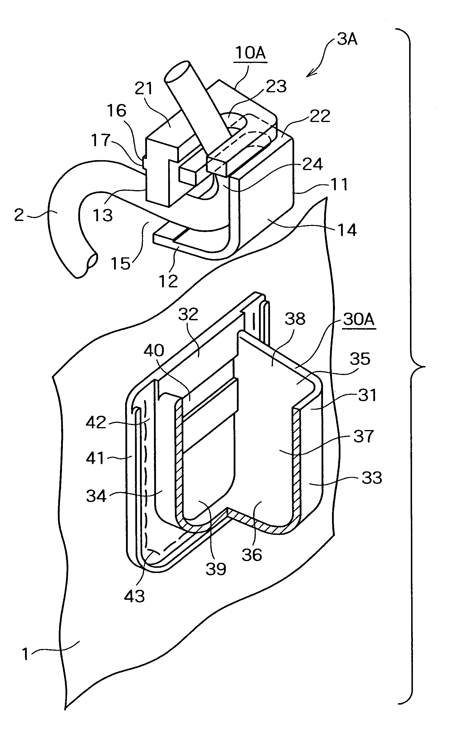
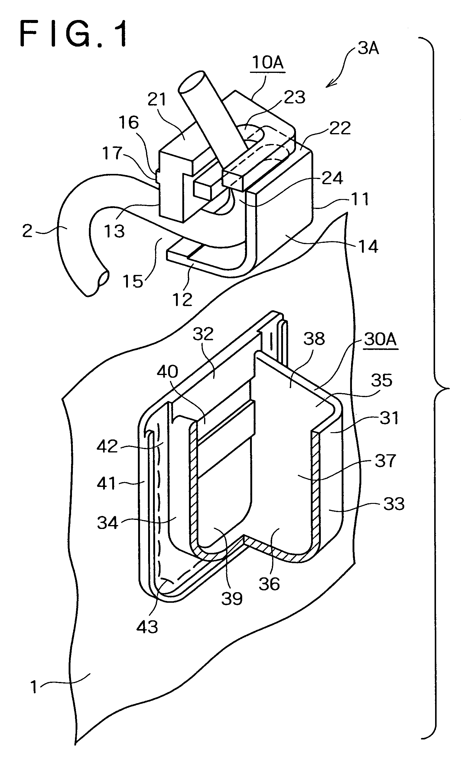
[0027]FIG. 1 is an exploded perspective view of a cord stopper according to the first embodiment of the present invention.

[0028]As shown in FIG. 1, the cord stopper 3A according to the first embodiment is comprised of a locking member 10A attached to a cord 2 which is in turn attached to an article 1 such as a garment; and a housing member 30A attached to the article 1 and adapted to house the locking member 10A therein.

[0029]If the article 1 is a garment, the cord 2 is provided along the edge of an opening such as a sleeve opening. An end of the cord 2 comes outward or inward through a hole formed in the article 1.

[0030]The locking member 10A is formed of relatively rigid materials such as polyacetal, polyamide, polypropylene, ABS resin, polycarbonate, etc. The housing member 30A is made of materials relatively softer and elastic (than that of the locking member 10A), such as polyurethane elastomer, olefin elastomer, po...

second embodiment

[0062]the present invention is shown in FIGS. 5 through 8.

[0063]FIG. 5 is an exploded perspective view showing the cord stopper 3B according to the second embodiment of the present invention.

[0064]The cord stopper 3B according to the second embodiment is different from the cord stopper 3A according to the first embodiment in the following points:

[0065]The opposed side walls 13, 14 of the locking member 10B according to the second embodiment is angularly oriented by 90 degrees relative to the opposed side walls 13, 14 of the locking member 10A according to the first embodiment. With this construction, when the opposed third and fourth side walls 34, 35 of the housing member proper 31 are pressed towards each other with this locking member 10B housed in the housing member proper 31, the opposed side walls 13, 14 elastically deform and bend towards each other. The third and fourth side walls 34, 35 facing the side walls 13, 14, respectively, of the locking member 1 are opposed to each ...

fifth embodiment

[0081]FIGS. 11 through 13 show the present invention.

[0082]FIG. 11 is an exploded perspective view showing a cord stopper 3E according to the fifth embodiment.

[0083]The cord stopper 3E according to the fifth embodiment differs from the cord stopper 3A according to the first embodiment in the following constructions of the locking member 10E and the housing member 30E.

[0084]The locking member 10E is comprised of a cylindrical socket 50 having an opening formed at one end, a plug 51 reciprocally disposed within the cylindrical socket 50, urging means such as a coil spring seated on the inner bottom of the socket 50 and adapted for urging the plug 51 in the direction tending to come out of the socket 50 and cord-inserting holes 53, 54 formed through the socket 50 and the plug 51, respectively. The coil spring 52 used as the urging means may be replaced by a resilient leg formed integrally at the lower end of the plug 51 and abutting on the inner bottom of the socket 50 so as to urge th...


PUM


Abstract

A cord stopper (3A˜3E) comprises a locking member (10A˜10E) adapted to be normally in locking engagement with a cord (2, 2A˜2C) and, when the locking member (10A˜10E) is pressed, to come out of locking engagement with the cord (2, 2A˜2C); and a housing member (30A˜30E) including a housing member proper (31A˜31E) adapted for housing the locking member (10A˜10E) therein and attached to an article (1). The housing member proper (31A˜31E) has a housing space (37, 37E) large enough to substantially accommodate the locking member (10A˜10E). Pressure applied to the housing member proper (31A˜31E) can be transmitted to the locking member (10A˜10E) through an outer wall of the housing space (37, 37E).

Description

BACKGROUND[0001]1. Field of the Invention[0002]This invention relates to a cord stopper for fixing any part of a cord to an article and particularly to a cord stopper comprising a locking member capable of normally be locking engagement with a cord, and coming out of locking engagement with the cord when the locking member is pressed, and a housing member adapted to house the locking member therein and attached to the article.[0003]2. Description of the Related Art[0004]A cord stopper is used for binding and releasing an opening of a sleeve of a garment or an opening of a bag. A conventional cord stopper is comprised of a cylindrical female member and a male member reciprocally mounted in the cylindrical female member. The male member is normally urged by separate urging means or urging means integrally formed with the male member in the direction tending to coming out of the female member. The female member and the male member have the respective through holes. Thrusting the male m...

Claims


Application Information

Patent Timeline
Patent Type & Authority Patents(United States)
IPC IPC(8): F16G11/00A44B21/00A44B99/00
CPCF16G11/10Y10T24/3713Y10T24/3984F16G11/101
Inventor KINEBUCHI, SHINICHIROSAITSU, NATSUKO
Owner YKK CORP
Why Eureka
Try Eureka