Boot for hydraulic, hydropneumatic or pneumatic piston-cylinder units

a technology for hydraulic, hydropneumatic or pneumatic pistons, applied in the direction of shock absorbers, vibration dampers, gas based dampers, etc., can solve the problems of failure of the piston-cylinder unit, water and dirt particles, even in small amounts, can enter the interior of the boot, etc., to reduce assembly, simple and safe manner, and economical piston rod protection

Inactive Publication Date: 2008-08-26
ZF FRIEDRICHSHAFEN AG
View PDF16 Cites 9 Cited by
  • Summary
  • Abstract
  • Description
  • Claims
  • Application Information

AI Technical Summary

Benefits of technology

[0004]An object of the present invention is to provide a boot for hydraulic, hydropneumatic or pneumatic piston-cylinder units such that, while reducing assembly and providing an economical piston rod protection, the boot operates without the use of a filter and water or dirt particles that may possibly enter may be removed in a simple and safe manner.
[0006]The solution has the advantage that the boot is provided with additional areas which ensure a labyrinth-like protective seal so that it is difficult for water and dirt particles from the atmosphere to reach the piston rod area and in the event that small amounts of water or dirt reach the interior of the boot they are eliminated quickly and completely.
[0009]In another embodiment, the boot and the area together form an open connection to the flow connection. This has the advantage that the area at least partially surrounds the boot coaxially.
[0013]To achieve a simple assembly and convenient storage, the areas and the boot are constructed in one piece.

Problems solved by technology

This construction has the disadvantage that water and dirt particles, even in small amounts, can enter the interior of the boot and remain there owing to the lack of an outlet opening.
As a result, the piston rod and the guide component are highly susceptible to corrosion, which can ultimately lead to failure of the piston-cylinder unit.

Method used


Image

  • Boot for hydraulic, hydropneumatic or pneumatic piston-cylinder units
  • Boot for hydraulic, hydropneumatic or pneumatic piston-cylinder units
  • Boot for hydraulic, hydropneumatic or pneumatic piston-cylinder units

Examples


Embodiment Construction

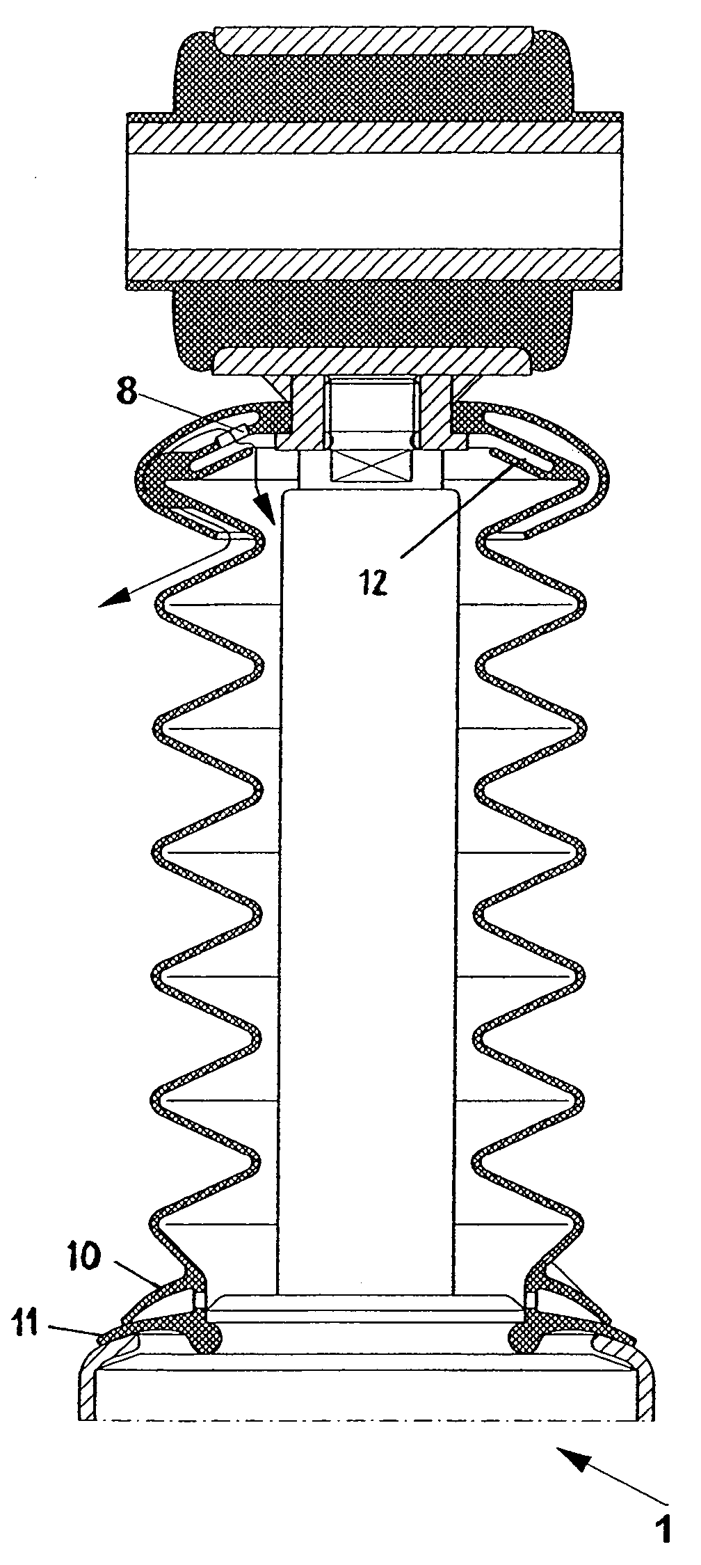
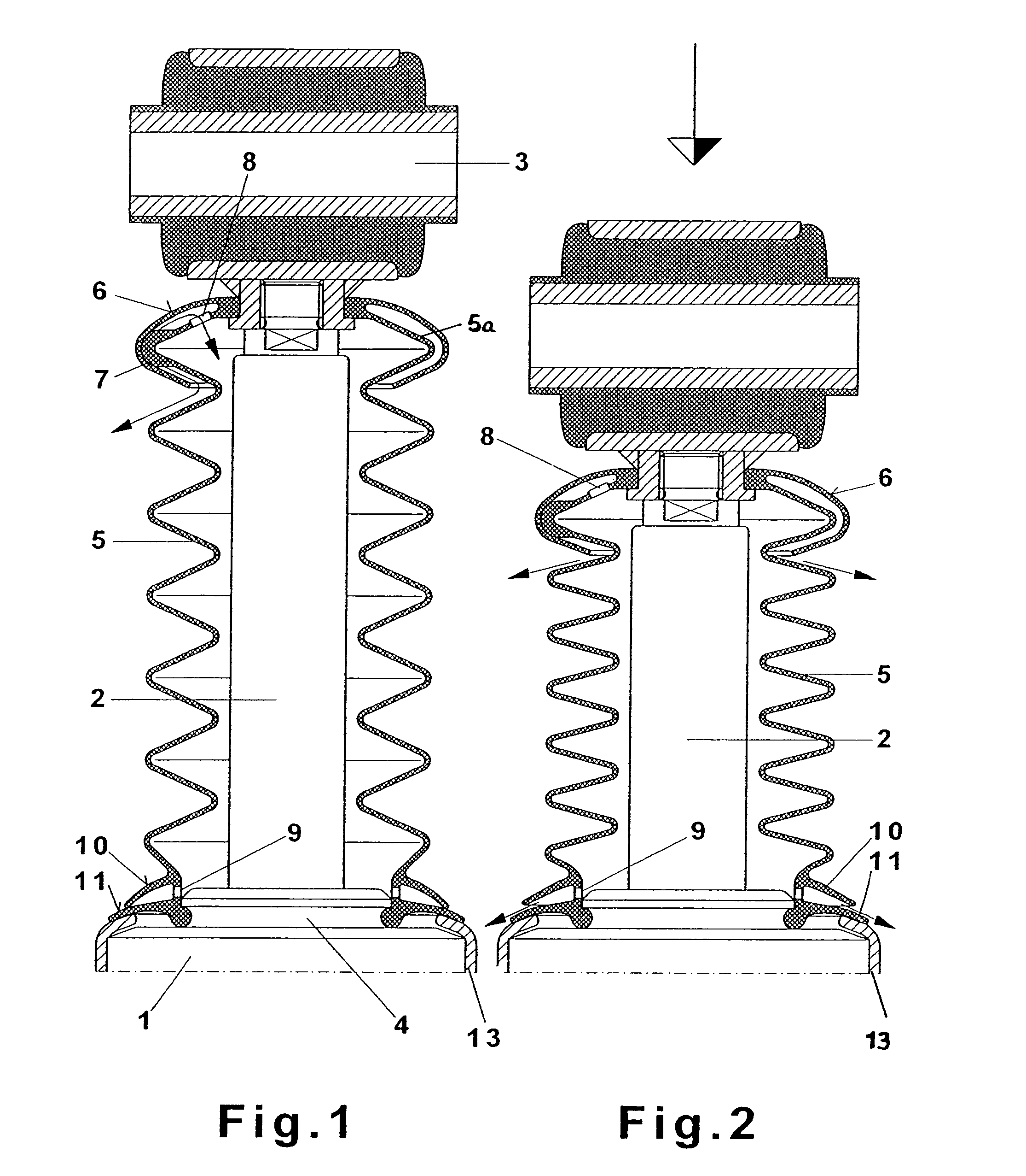
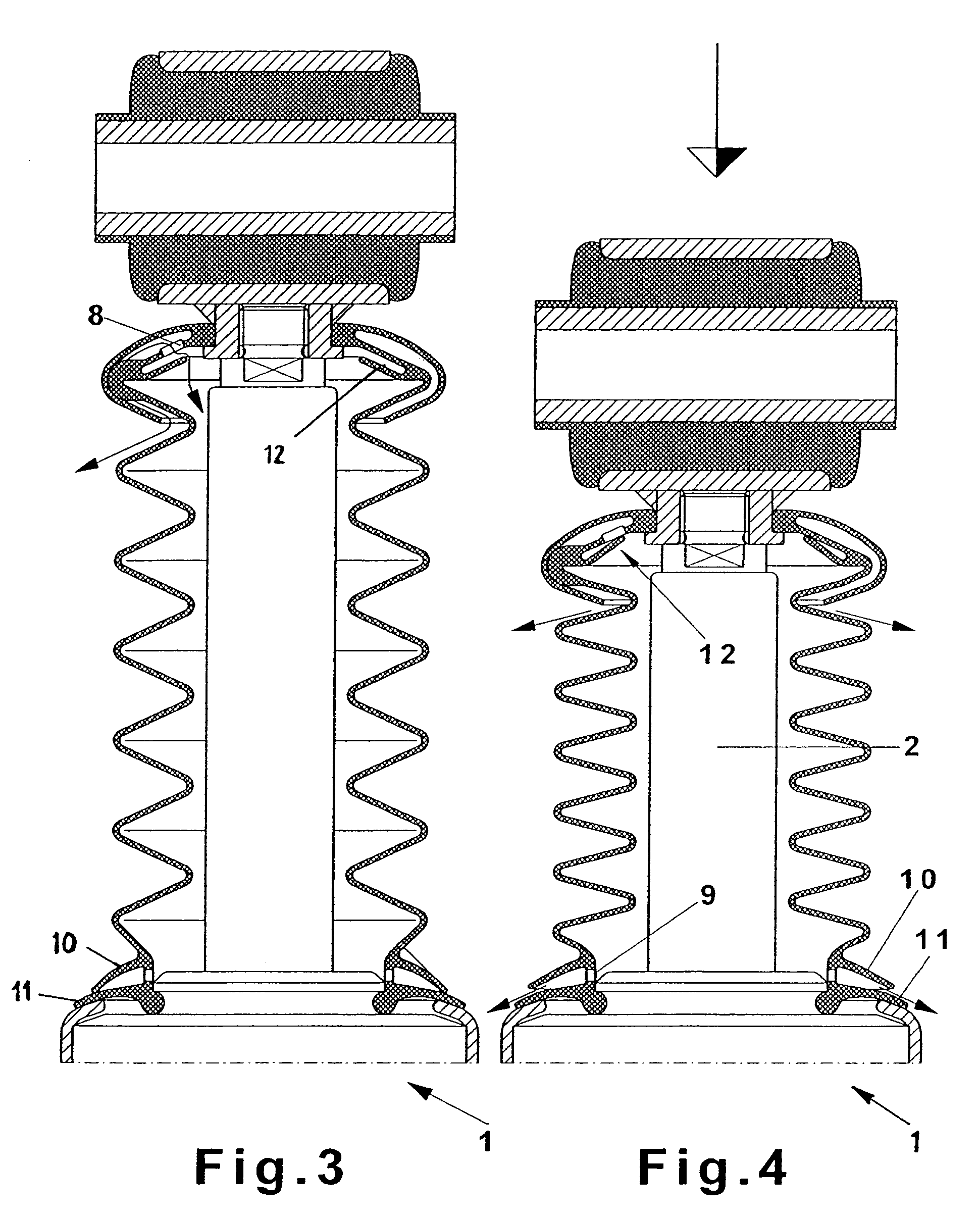
[0022]The piston-cylinder unit 1 in FIGS. 1 and 2 substantially comprises a container tube 13 in which individual parts (not shown in more detail) of a vibration damper are located. A piston rod 2 projects out of the container tube 13 and a fastening part 3 for fastening to a vehicle is located at the upper end of the piston rod 2. A piston rod guide 4 at the end of the container tube 13 guides the piston rod 2 so that the piston rod 2 is axially movable in the interior of the container tube 13.

[0023]Between the fastening part 3 and the piston rod guide 4, the boot 5 is tightly arranged at corresponding fastening points to protect the piston rod 2 from water, dust and stone debris. In the upper area of the boot 5, an area 6 comprises a first fold 5a of the boot 5 and is supported on a plurality of nubs 7 which are uniformly distributed around the circumference on the first fold 5a. It is difficult for dirt and water from the atmosphere to penetrate into the boot 5 at this location b...


PUM


Abstract

A boot for a hydraulic, hydropneumatic or pneumatic piston-cylinder unit, in particular for vibration dampers or spring struts for vehicles, covers a portion of a piston rod that projects from the cylinder of the piston-cylinder unit. To protect against dirt and / or damage, the boot is arranged between the end of the piston rod and the cylinder. The interior space of the boot undergoes a change in volume due to the relative movement of the piston rod and cylinder with respect to one another. At least one flow connection is provided which leads to the interior space of the boot and allows for air flow in and / or out of the interior space. The at least one flow connection is at least partly covered by an area of the boot.

Description

BACKGROUND OF THE INVENTION[0001]The present invention is directed to a bellows or boot for hydraulic, hydropneumatic or pneumatic piston-cylinder units, and particularly for vibration dampers or spring struts for vehicles, wherein the boot covers the portion of the piston rod that projects from the cylinder to protect against dirt and / or damage and is arranged between the end of the piston rod and the cylinder, the interior space of the boot undergoes a change in volume due to the relative movement of the parts with respect to one another, and at least one flow connection is provided which leads to the interior space of the boot and allows air to flow in and / or out.[0002]Boots for piston-cylinder units in which a vibration damper or a spring strut is provided with a boot for protecting against dirt and / or damage are already known from German patent document DE 102 00 608 A1. Due to the relative movement between the piston rod and the cylinder, the interior space of the boot undergo...

Claims


Application Information

Patent Timeline
Patent Type & Authority Patents(United States)
IPC IPC(8): F16F9/38
CPCF16F9/38
Inventor BECK, HUBERT
Owner ZF FRIEDRICHSHAFEN AG
Why Eureka
Try Eureka