Electronic equipment module mounting apparatus and method

a technology of electronic equipment and mounting devices, which is applied in the direction of electrical apparatus, support structure mounting, electrical apparatus casings/cabinets/drawers, etc., can solve the problems of increased installation, repair and replacement difficulty, increased cost, and increased risk of communication line failur

Active Publication Date: 2008-08-26
GARMIN INT
View PDF91 Cites 52 Cited by
  • Summary
  • Abstract
  • Description
  • Claims
  • Application Information

AI Technical Summary

Benefits of technology

[0012]In one embodiment, an electronic equipment module is provided which can be installed and removed without using tools. The module includes a chassis unit which slides into a unit rack, which in turn is attached to a mounting frame. The entire assembly is typically mounted to a surface, such as the instrument panel of an aircraft. The module is placed into electrical communication with the unit rack via mating connectors attached to the module and to the unit rack using a pivoting cam lever and engagement lug. The lever/lug combination, which i

Problems solved by technology

Because of the limited space available on any given aircraft, designers and manufacturers tend to locate avionics modules in areas of the aircraft where space is at less of a premium.
However, such locations make installation, repair, and replacement more difficult, and more expensive.
Longer communication lines increase the difficulty of installation, as well as the risk of communication line failure due to vibration, physical movement, and other factors.
Such configurations reduce problems due to long communication lines, howeve

Method used


Image

  • Electronic equipment module mounting apparatus and method
  • Electronic equipment module mounting apparatus and method
  • Electronic equipment module mounting apparatus and method

Examples


Embodiment Construction

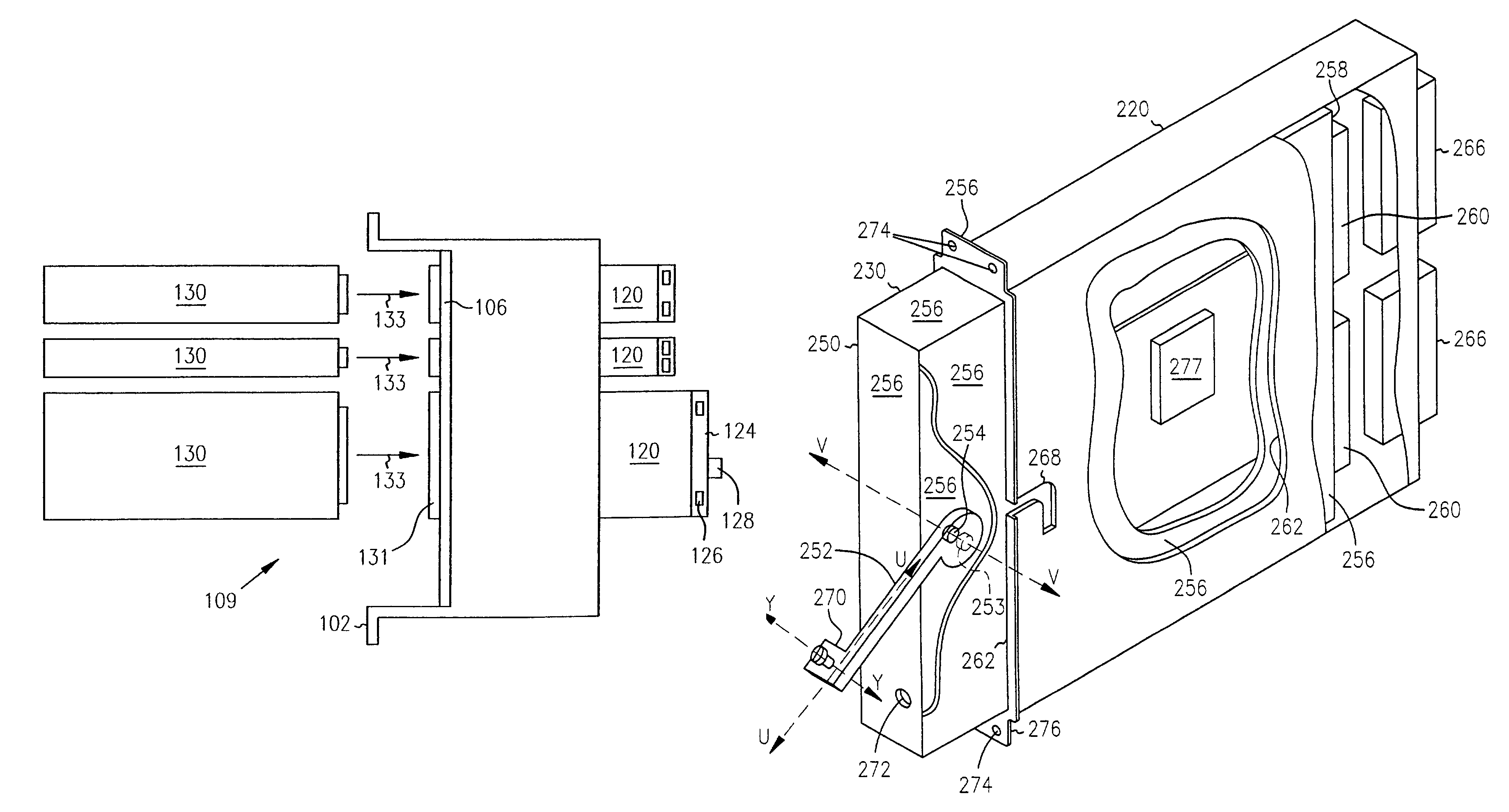
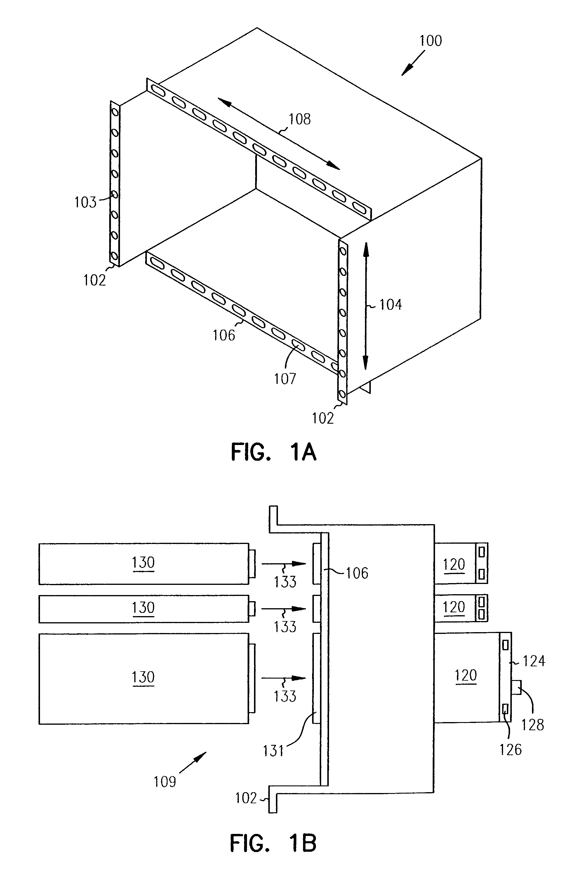
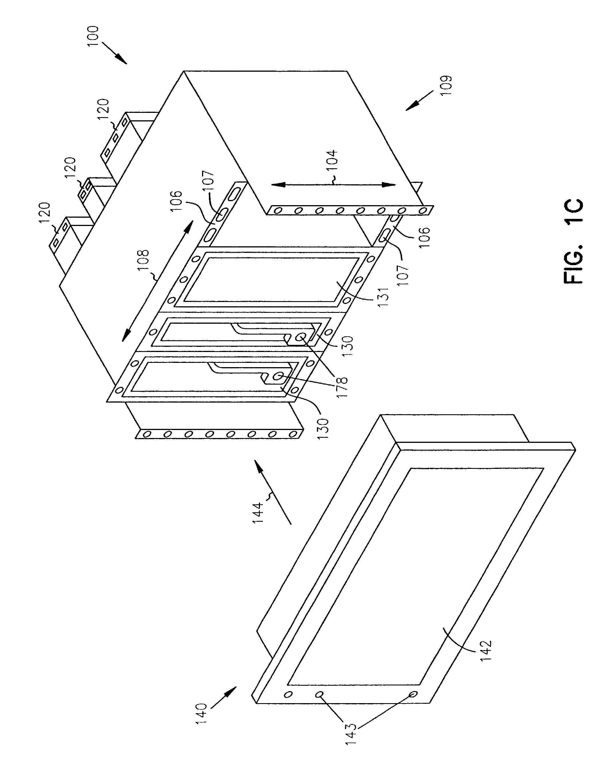
[0026]In the following detailed description of the invention, reference is made to the accompanying drawings which form a part hereof, and in which is shown, by way of illustration, specific embodiments in which the invention can be practiced. In the drawings, like numerals describe substantially similar components throughout the several views. These embodiments are described in sufficient detail to enable those skilled in the art to practice the invention. Other embodiments can be utilized and structural, logical, and electrical changes can be made without departing from the scope of the present invention.

[0027]References to directions, such as up, down, above, or below, etc. will have their normal meaning with the ground being downward when referring to embodiments not used in aircraft. When referring to embodiments mounted to an aircraft, downwards will refer to the direction towards the floor of the aircraft (i.e., to which the landing gear is typically mounted), regardless of t...


PUM


Abstract

An equipment module, a module retention device, as well as a system and a method for mounting equipment modules are disclosed. The modules can be installed without tools, using the retention device. Each module includes a chassis unit which slides into a unit rack, which is in turn attached to a mounting frame. The entire assembly may be mounted to an instrument panel. The module retention device is attached to the chassis unit, typically engaging a slot on the rack. A rotating fastener secures the retention device in the engaged position. The method includes inserting an electronic module into the open end of a unit rack, sliding an engagement lug attached to a cam lever into engagement with a slot on the rack, electrically coupling a connector on the module with a connector on the rack, and attaching the rack to the mounting frame.

Description

RELATED APPLICATION[0001]This application is a continuation of application Ser. No. 10 / 086,482 filed Feb. 28, 2002, now U.S. Pat. No. 6,549,424 which is incorporated herein by reference.FIELD OF THE INVENTION[0002]The invention relates generally to mounting devices and methods of mounting electronic equipment. More particularly, the invention relates to mounting devices and methods of mounting avionic equipment in an aircraft.BACKGROUND OF THE INVENTION[0003]Electronic equipment and devices in general can be incorporated into increasingly smaller packages. In the aviation industry, instrumentation and other electronic equipment operates in an increasingly integrated and autonomous fashion. Such equipment, termed “avionics”, or the electronic instrumentation devices used in an aviation setting, including electronic sensors, communications equipment, navigation equipment, and displays, is therefore also subject to trends in miniaturization and integration, as used in aircraft of all s...

Claims


Application Information

Patent Timeline
IPC IPC(8): H05K5/00H05K7/14
CPCH05K7/1409
Inventor BESETH, JEFFREY L.COOL, DANIEL J.ROLLHEISER, PAUL J.WHEATON, SHELDON T.RUFF, BRIAN F.KLEIN, JARED S.
Owner GARMIN INT
Why Eureka
Try Eureka