Signal processing apparatus, signal processing program and electronic camera

a signal processing and signal processing technology, applied in the field of signal processing technology, can solve the problems of false signal, noise, uneven signal processing, etc., and achieve the effect of suppressing harmful effects, excellent spatial frequency filter processing, and suppressing noise of feature information

Inactive Publication Date: 2008-08-26
NIKON CORP
View PDF14 Cites 68 Cited by
  • Summary
  • Abstract
  • Description
  • Claims
  • Application Information

AI Technical Summary

Benefits of technology

[0020]Then, it is another object of the invention to improve the problems of the noise when the intensity of the spatial frequency filter is adjusted.
[0095]Further, between the adjacent pixels, since most of the set local areas overlap with each other, the feature information is not abruptly changed. Accordingly, there is little fear that the coefficient group of the spatial frequency filter is abruptly changed between the adjacent pixels. As a result, it is possible to suitably suppress such harmful effects that a false boundary and a false color are generated by an extensive change of the spatial frequency filter.

Problems solved by technology

In the case where the spatial frequency filter is adjusted in accordance with the above object, there arises a problem that a signal processing varies excessively by noise included in the pixel signal, and the noise becomes noticeable by the variation.
There arises a problem that in these places, unevenness of the signal processing becomes a false signal (noise) and noticeable.

Method used


Image

  • Signal processing apparatus, signal processing program and electronic camera
  • Signal processing apparatus, signal processing program and electronic camera
  • Signal processing apparatus, signal processing program and electronic camera

Examples


embodiment

[Description of Structure of Embodiment]

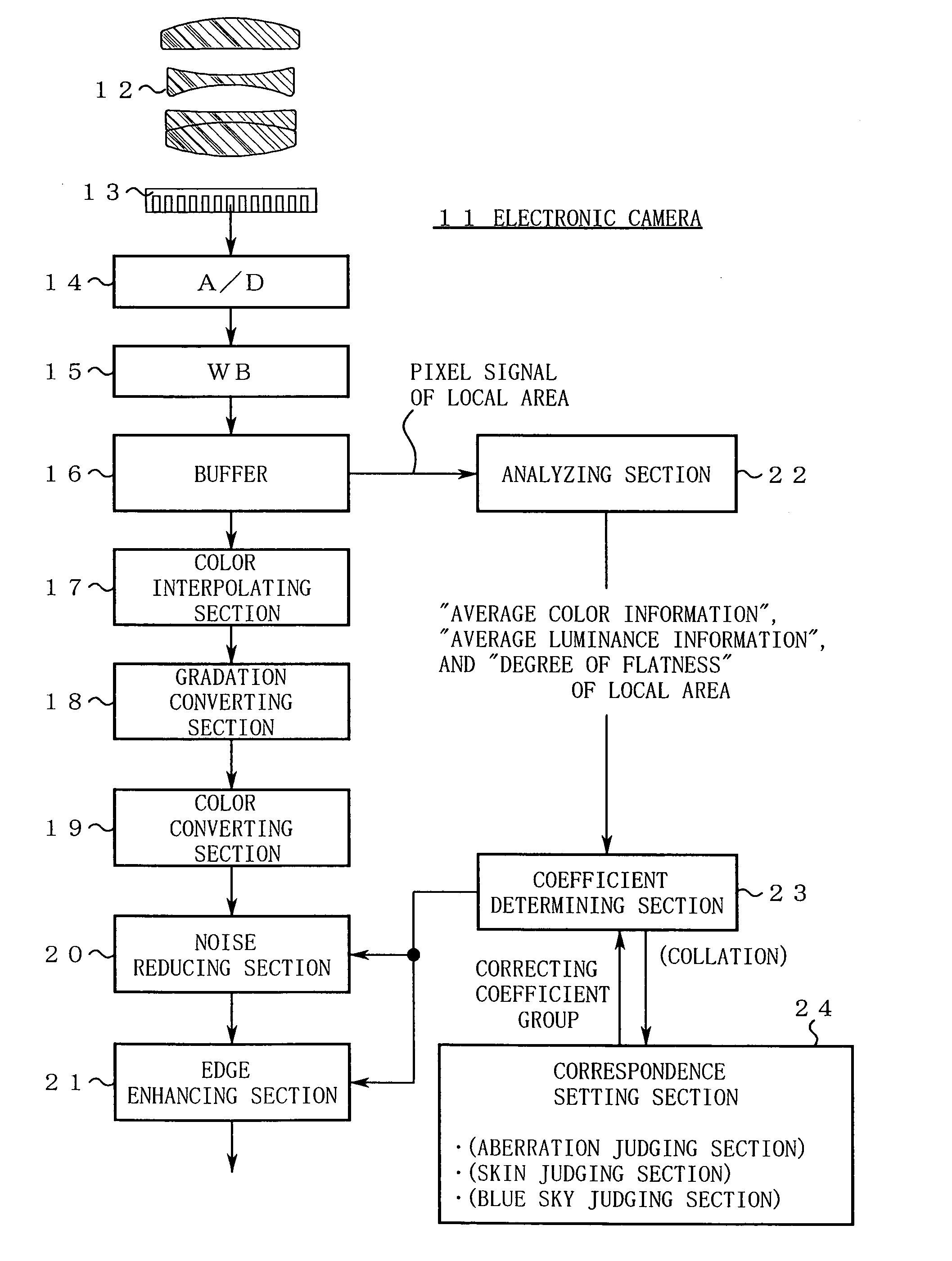
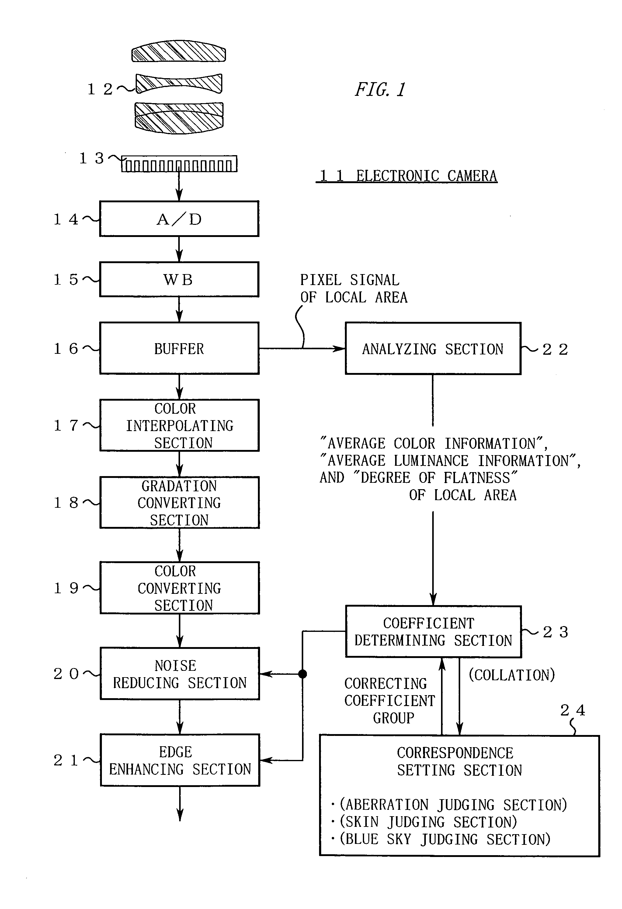
[0104]FIG. 1 is a block diagram showing an electronic camera 11 of this embodiment.

[0105]In FIG. 1, a taking lens 12 is mounted in the electronic camera 11. An image pickup plane of an image pickup element 13 is disposed in an image space of the taking lens 12. A pixel signal scan-outputted from the image pickup element 13 is processed through an A / D conversion part 14 and a white balance adjustment part 15, and then is stored as image data in a buffer 16.

[0106]The image data in the buffer 16 is processed through a color interpolating section 17, a gradation converting section 18, a color converting section 19, a noise reduction section 20, and an edge enhancing section 21, and then is compressed and recorded in a not-shown recording medium.

[0107]Further, the electronic camera 11 includes an analyzing section 22, a coefficient determining section 23, and a correspondence setting section 24.

[0108]The analyzing section 22 and the coefficient det...


PUM


Abstract

A signal processing apparatus includes a signal processing section applying a spatial frequency filter to a pixel signal to perform a signal processing of noise reduction and / or edge enhancement, and a coefficient correcting section setting a coefficient group of the spatial frequency filter to a correct coefficient group. The coefficient correcting section includes an analyzing section, a correspondence section and a coefficient determining section. The analyzing section sets a local area to include an object pixel of the signal processing, and obtains average color information. A correspondence relation between the average color information and the correct coefficient group is set beforehand in the correspondence setting section. The coefficient determining section checks the correspondence relation of the correspondence setting section on the basis of the average color information obtained by the analyzing section, and adjusts the correct coefficient group used for the pixel of the processing object.

Description

CROSS REFERENCE TO RELATED APPLICATION[0001]This application is based upon and claims the benefit of priority from Japanese Patent Application No. 2003-189521, filed on Jul. 1, 2003, the entire contents of which are incorporated herein by reference.BACKGROUND OF THE INVENTION[0002]1. Field of the Invention[0003]The present invention relates to a signal processing technology applied to an imaging apparatus such as an electronic camera, a video camera, a scanner and a printer.[0004]2. Description of the Related Art[0005]In general, an imaging apparatus has something that applies a spatial frequency filter to a pixel signal in order to perform edge enhancement and noise reduction.[0006]For example, as a spatial frequency filter for noise reduction, there is known a method in which a 3×3 pixel block around the pixels of the processing object is cut out, having the pixels of the processing object in the center, the pixel block is multiplied by a coefficient group of[0007]1 1 1[0008]1 2 1...

Claims


Application Information

Patent Timeline
Patent Type & Authority Patents(United States)
IPC IPC(8): G06K9/00G06T5/00G06T5/20G06T7/00H04N1/409H04N1/46H04N5/208H04N5/21H04N9/07H04N9/64H04N9/68
CPCG06T5/20H04N1/409H04N1/58G06T5/003G06T5/002G06T2207/20192G06T2207/10024
Inventor HOSHUYAMA, HIDEO
Owner NIKON CORP
Why Eureka
Try Eureka