Control apparatus for direct injection type internal combustion engine

a technology of control apparatus and internal combustion engine, which is applied in the direction of electrical control, process and machine control, etc., can solve the problems of fuel injection control error and inability to achieve control precision, and achieve the effect of high precision air-fuel ratio control, improved drivability, and reduced harmful chemical substances in the exhaust gas

Active Publication Date: 2008-08-26
HITACHI ASTEMO LTD
View PDF6 Cites 16 Cited by
  • Summary
  • Abstract
  • Description
  • Claims
  • Application Information

AI Technical Summary

Benefits of technology

[0009]Through the above described control, an internal combustion engine can be provided which, without resort to additional actuators and sensors, realizes accurate fuel injection control irrespective of the change in the fuel pressure in the fuel rail fluctuating due to the fuel discharge from the high-pressure fuel pump and the fuel injection from the injectors. Accordingly, high precision air-fuel ratio control can be achieved for the internal combustion engine and therefore improved drivability can be achieved and harmful chemical substances in the exhaust gas can be reduced.

Problems solved by technology

In the case where the previous measurement of the change in the fuel pressure is reflected in the following control of the fuel injection, however, control precision cannot be attained and error in the control of fuel injection may be caused, if change occurs in the injection pulse width, the fuel injection timing of the injectors or the start timing of discharging fuel by the fuel pump.

Method used


Image

  • Control apparatus for direct injection type internal combustion engine
  • Control apparatus for direct injection type internal combustion engine
  • Control apparatus for direct injection type internal combustion engine

Examples


Embodiment Construction

[0030]This invention will now be described in detail by way of an embodiment with reference to the attached drawings.

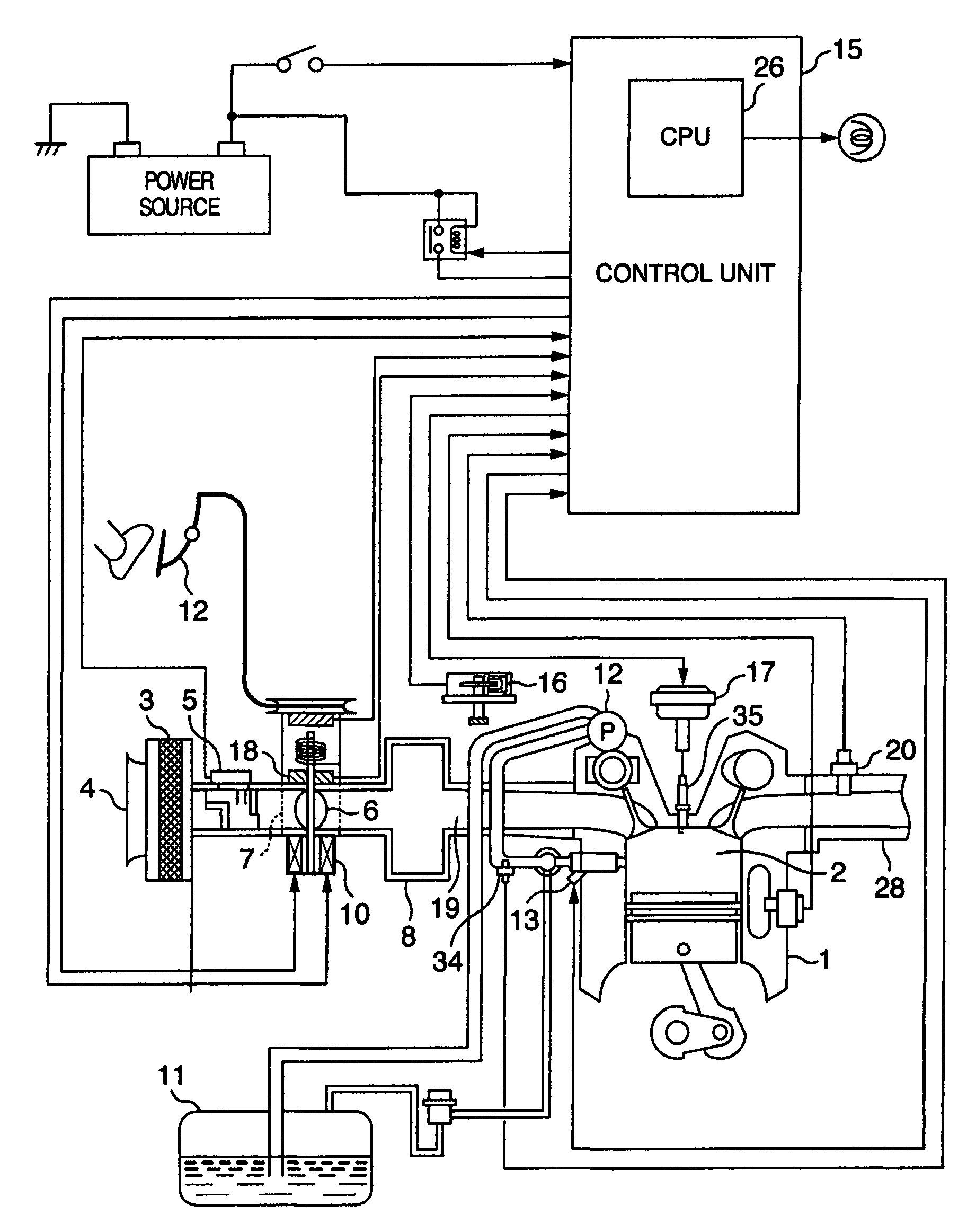
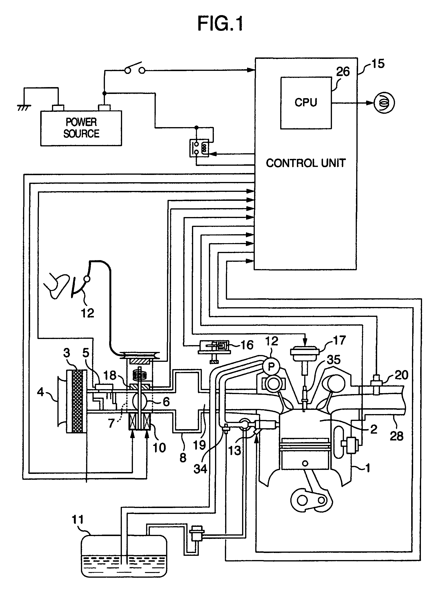
[0031]FIG. 1 shows a control system for a direct injection type internal combustion engine (hereafter referred to also as “engine”) according to this invention. In FIG. 1, air to be drawn into an engine 1 first enters the inlet 3 of an air cleaner 4, and passes through an air flow sensor 5 and a throttle body 7 having therein a throttle valve 6 for controlling the intake air flow, into a collector 8. The throttle valve 6 is mechanically connected with a driving motor 10. The operation of the motor 10 actuates the throttle valve 6 to control the intake air flow.

[0032]The intake air in the collector 8 is then distributed to air inlet pipes 19 communicating with the cylinders 2 of the engine 1, and then fed into the cylinder 2 serving as a combustion chamber.

[0033]Fuel such as gasoline is sucked up from a fuel tank 11 and pressurized, by means of a fuel pump 12. The pres...


PUM


Abstract

An apparatus for controlling the quantity of fuel injection of injectors in accordance with the fuel pressure in the fuel rail of a direct injection type internal combustion engine, including a fuel injection quantity calculating section for calculating the quantity of fuel injection of the injector, a fuel discharge quantity calculating unit for calculating the quantity of fuel discharged from the high-pressure fuel pump into the fuel rail, and a difference calculating unit for calculating the difference between the quantity of fuel injected out of the injector calculated by the fuel injection quantity calculating section and the quantity of fuel discharged from the high-pressure fuel pump into the fuel rail calculated by the fuel discharge quantity calculating unit, wherein the reference value for controlling the injector is obtained on the basis of the difference and the fuel pressure in the fuel rail at the time of starting fuel injection out of injector, and the injector is controlled depending on the reference value.

Description

BACKGROUND OF THE INVENTION[0001]This invention relates to a control apparatus for a direct injection type internal combustion engine.[0002]An accumulator type fuel injection control apparatus is well known as an apparatus for feeding fuel into the plural cylinders of a direct injection type internal combustion engine. According to this type of fuel injection control apparatus, fuel is pressurized in the fuel rail (common rail) by the use of a fuel pump and then is injected into the cylinders through the injectors mounted on the fuel rail. Further, this fuel injection control apparatus makes it possible to obtain such an optimal fuel injection quantity as to stabilize fuel combustion by making the pressure of fuel in the rail variable.[0003]With the accumulator type fuel injection control apparatus as described above, the pressure of the fuel in the fuel rail (hereafter also referred to simply as “fuel pressure”) pulsates due to the feed (hereafter referred to also as “discharge”) o...

Claims


Application Information

Patent Timeline
Patent Type & Authority Patents(United States)
IPC IPC(8): F02D41/30G06F19/00F02D41/04F02D41/14F02D41/32F02D45/00
CPCF02D41/3836F02D35/023F02D41/3845
Inventor TOYOHARA, MASAHIROOKAMOTO, TAKASHIHASEGAWA, MICHIHIKO
Owner HITACHI ASTEMO LTD
Why Eureka
Try Eureka