Pneumatic tool

a technology of pneumatic tools and stapling tools, which is applied in the field of pneumatic tools, can solve the problems of shortening the shelf life and easy breakage of the conventional structure, and achieve the effect of prolonging the life of the produ

Inactive Publication Date: 2008-09-02
BASSO IND CORP
View PDF4 Cites 15 Cited by
  • Summary
  • Abstract
  • Description
  • Claims
  • Application Information

AI Technical Summary

Benefits of technology

[0011]In addition, the present invention uses structures, such as the internal and external valve base 3040 and traveling valve 50 of built-in check valve B, so that the internal and external tapered protruding end 5152 for the traveling valve 50 can induce and block the air as expected, making simpler manufacturing, convenient assembly and stable movement.

Problems solved by technology

Except, it is found that the conventional structure is easily broken due to the external force of using the check valve 01 and its pipe 04, which shortens the shelf life.

Method used


Image

  • Pneumatic tool
  • Pneumatic tool
  • Pneumatic tool

Examples


Embodiment Construction

[0020]The features and the advantages of the present invention will be more readily understood upon a thoughtful deliberation of the following detailed description of a preferred embodiment of the present invention with reference to the accompanying drawings.

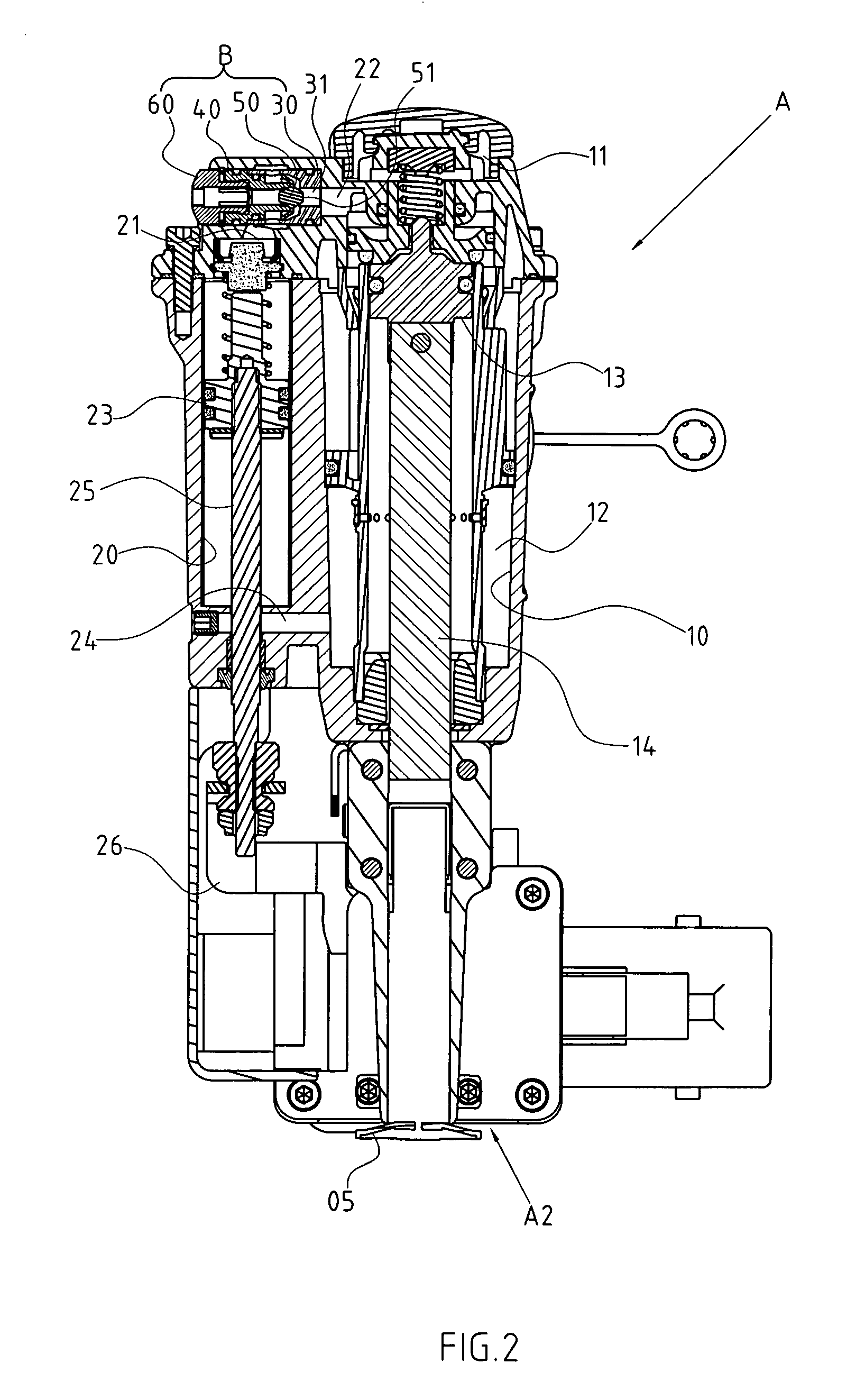
[0021]As shown in FIGS. 2-4, there is a preferred embodiment of the pneumatic tool A, a nailer.

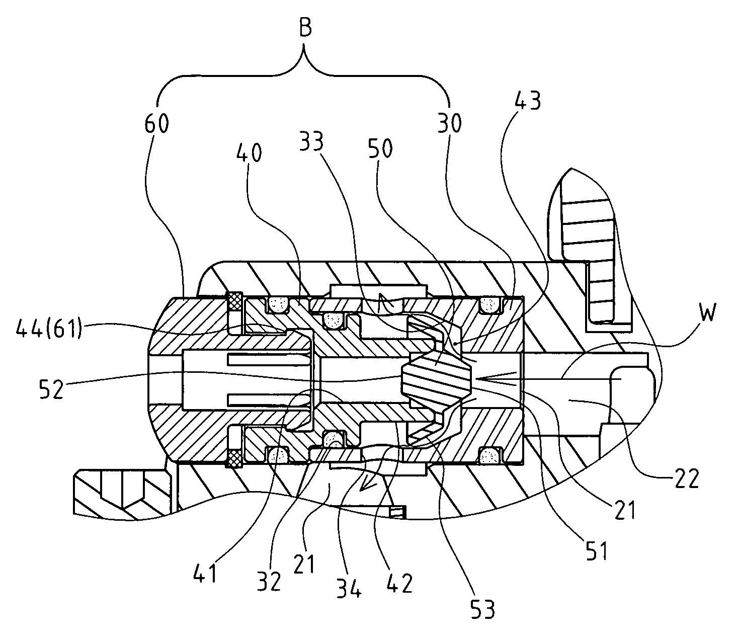
[0022]A first cylinder 10 is placed inside the pneumatic tool A, and the first cylinder 10 includes an air inlet 11 and a lower air chamber 12 (the present embodiment is the through hole style that is placed on the wall of the first cylinder). A first piston 13 is placed inside the first cylinder 10, and in the present embodiment, the first piston 13 drives the striker pin 14 to make the expected nailing movement.

[0023]A second cylinder 20 is a supply cylinder, and it is placed on the first cylinder 10 inside the pneumatic tool A and spaced from the first cylinder. The air inlet 21 of the second cylinder 20 is connected to the air inle...


PUM


Abstract

The pneumatic tool has a check valve placed inside that includes an internal and external valve base and traveling valve. The internal valve base has an inlet hole, and an enlarged slot is formed on the external end of the inlet hole. An annular oblique edge is formed between the enlarged slot and inlet hole, and an air hole is placed on the enlarged slot. The external valve base has an outlet hole that is connected to the outside of the pneumatic tool. A protruding tube is formed inside the outlet hole. Interval space is formed between the inside of the protruding tube and the inlet hole for the internal valve base; and the traveling valve can be traveling inside the interval space. The built-in check valve can avoid external force, which extends the shelf life and makes appearance of the product look neater and practical.

Description

RELATED U.S. APPLICATIONS[0001]Not applicable.STATEMENT REGARDING FEDERALLY SPONSORED RESEARCH OR DEVELOPMENT[0002]Not applicable.REFERENCE TO MICROFICHE APPENDIX[0003]Not applicable.FIELD OF THE INVENTION[0004]The present invention relates generally to a pneumatic tool, and more particularly to a device that has a check valve for an air inlet and outlet between the first and second cylinder.BACKGROUND OF THE INVENTION[0005]The conventional pneumatic nail gun uses a single cylinder and piston to accomplish the nailing function.[0006]Some nail guns have other functions besides a nailing function, such as sending the pad to the nail outlet when nailing so that there is an extra padding effect after the nail is sent. These nail guns satisfy multiple needs of the users, and there is a typical embodiment. So as to implement these multiple functions, the industry usually adds a second cylinder and piston on one side of the original cylinder (hereafter referred to as first cylinder) to dri...

Claims


Application Information

Patent Timeline
Patent Type & Authority Patents(United States)
IPC IPC(8): B25C1/04
CPCB25C5/1693
Inventor CHEN, JACKWANG, JIM
Owner BASSO IND CORP
Why Eureka
Try Eureka