Dehumidifier safety cut-off system

a technology of dehumidifier and safety cut-off, which is applied in the direction of heating types, space heating and ventilation details, and domestic heating details, etc., can solve the problems of dehumidifier apparatus not having an additional safety, not providing an alternative shutoff in the event of condenser pump failure,

Inactive Publication Date: 2008-09-02
LANDES ROCK +1
View PDF13 Cites 8 Cited by
  • Summary
  • Abstract
  • Description
  • Claims
  • Application Information

AI Technical Summary

Problems solved by technology

While the Powell patent has features that provide an adjustable float for setting the moisture level shutoff, it does not provide an alternative shutoff in the event of condenser pump failure.
However, the dehumidifier apparatus of the Anderson patent does not feature an additional safety feature that would shut of the condenser in the event of a failure.
While the Forsberg patent has numerous subsystems that will disable the generator, the potable-water generator of the Forsberg patent does not provide a secondary safety device.
(U.S. Pat. No. Des. 310,412) discloses an ornamental design for a dehumidifier, which fails to illustrate any type of safety measures for preventing water spillage in the event of a malfunction.
However, the dehumidifier is designed to include a shutoff switch, and not directed to an after-market accessory purchased for the specific purpose of acting as a second safety shut-off switch.

Method used


Image

  • Dehumidifier safety cut-off system
  • Dehumidifier safety cut-off system
  • Dehumidifier safety cut-off system

Examples


Embodiment Construction

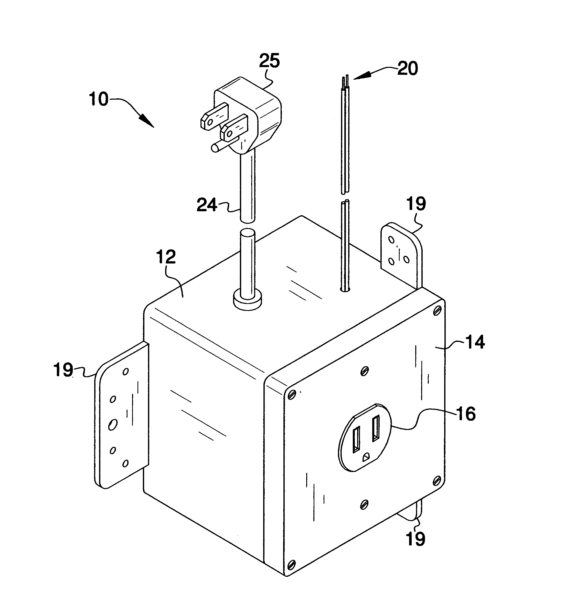
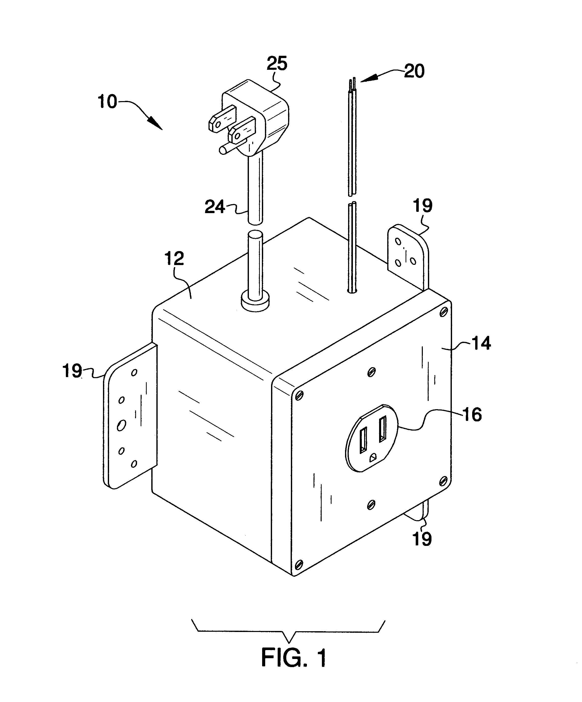
[0021]Detailed reference will now be made to the present invention, examples of which are illustrated in FIGS. 1-5. a dehumidifier safety cut-off system 10 (hereinafter invention) which includes a receptacle connection box 12, that has a box cover 14 with a receptacle outlet 16 to supply power to a dehumidifier 23. The receptacle connection box 12 also has a pair of mounting plates 19 and a pair of low voltage wires 20 that attach to a safety float switch of a condensate pump 22. The receptacle connection box 12 is powered by a power cord 24, which contains a plug 25 at the end of the power cord 24.

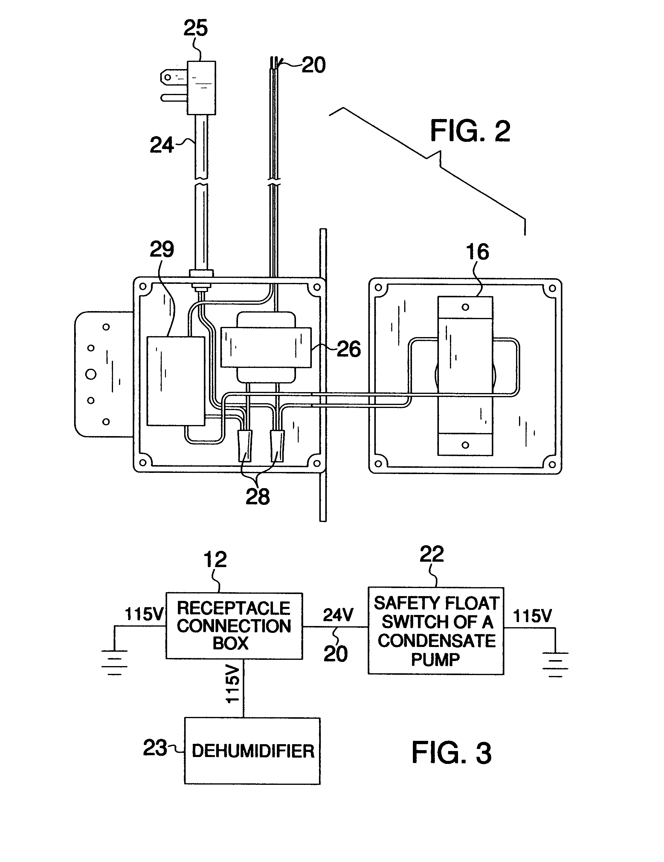
[0022]Referring to FIG. 2, a transformer 26 is wired by a pair of crimp caps 28 to a relay 29, the power cord 24, and the receptacle 16. The left low voltage wire 20 is wired to the relay 29 and the right low voltage wire 20 is wired to the transformer 26.

[0023]The power cord 24 powers the transformer 26, which in turn powers the low voltage wiring 20 at a reduced wattage or voltage. The ...


PUM


Abstract

The present invention relates to a dehumidifier safety cut-off system. This invention is an after-market safety accessory for existing dehumidifiers which operate through the use of a condensate-pump. The safety cut-off system would automatically shut down a dehumidifier in the event of pump failure by disabling the power supply to the dehumidifier. This system would consist of a compact housing with an external power cord, a transformer, a normally closed relay, and a pair of external, low voltage leads that would be connected to the safety float switch leads of the condensate pump. The invention could also feature an alternative version that could be hard wired in place.

Description

CROSS REFERENCE TO RELATED APPLICATIONS[0001]Not ApplicableSTATEMENT REGARDING FEDERALLY SPONSORED RESEARCH[0002]Not ApplicableREFERENCE TO APPENDIX[0003]Not ApplicableBACKGROUND OF THE INVENTION[0004]A. Field of the Invention[0005]The present invention relates to a dehumidifier safety cut-off system. This invention is a safety accessory for dehumidifiers which operate through the use of a condensate-pump.[0006]B. Discussion of the Prior Art[0007]The Powell et al. patent (U.S. Pat. No. 5,884,495) discloses a dehumidifier comprising of an adjustable float with a variable height cam surface that is in contact with the actuator on an interlock switch, which controls the supply of power to the refrigeration system of the dehumidifier. While the Powell patent has features that provide an adjustable float for setting the moisture level shutoff, it does not provide an alternative shutoff in the event of condenser pump failure. The present invention differs from the dehumidifier of the Powe...

Claims


Application Information

Patent Timeline
Patent Type & Authority Patents(United States)
IPC IPC(8): H01R13/66
CPCF24F13/222
Inventor LANDES, ROCKLANDES, SAM
Owner LANDES ROCK
Why Eureka
Try Eureka