Microfluidic device for enabling fluidic isolation among interconnected compartments within the apparatus and methods relating to same

a microfluidic device and fluid isolation technology, applied in the field of nanotechnology, can solve problems such as not always advantageous

Active Publication Date: 2008-09-02
RGT UNIV OF CALIFORNIA
View PDF10 Cites 67 Cited by
  • Summary
  • Abstract
  • Description
  • Claims
  • Application Information

AI Technical Summary

Benefits of technology

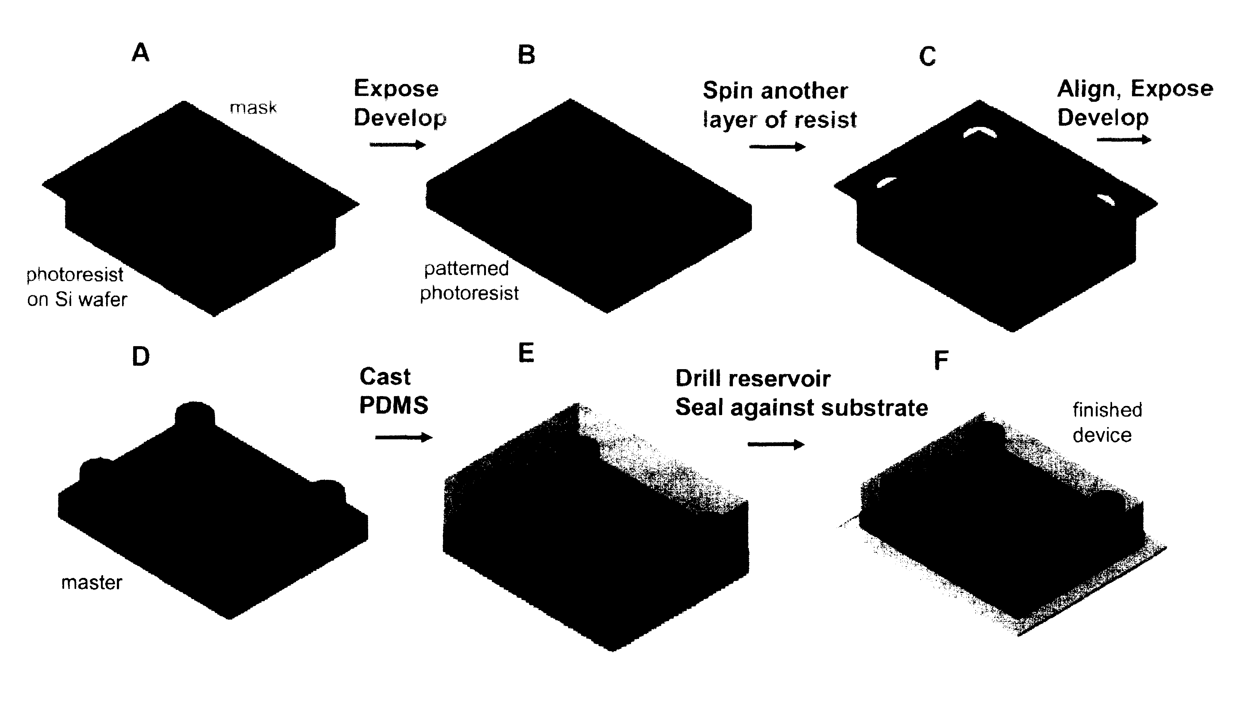
[0012]Visualization and identification of neurons is feasible using poly-lysine patterning in combination with the microfluidic device. In one or more instances, the device is constructed to have multiple chambers. At least one of these chambers is configured to direct the sites of neuronal attachment and the orientation of neurite outgrowth by micropatterning techniques, combined with fluidically isolated compartments with the culture area. The ability to direct the sites of neuronal attachment and the orientation of neurite outgrowth by micropatterning techniques, combined with fluidically isolated compartments within the culture area offer significant advantages over standard open culture methods and other conventional methods for manipulating distinct neuronal microenvironments. The device may have two or more compartments thereby allowing the application of substances to more than one neurite location and can be applied to neuronal and non-neuronal cells.

Problems solved by technology

However, for purposes of conducting experiments this is not always advantageous.

Method used


Image

  • Microfluidic device for enabling fluidic isolation among interconnected compartments within the apparatus and methods relating to same
  • Microfluidic device for enabling fluidic isolation among interconnected compartments within the apparatus and methods relating to same
  • Microfluidic device for enabling fluidic isolation among interconnected compartments within the apparatus and methods relating to same

Examples


Embodiment Construction

[0025]Embodiments of the invention are directed to a Microfluidic Multi-Compartment Device for Neuroscience or other Research. In the following exemplary description numerous specific details are set forth in order to provide a more thorough understanding of embodiments of the invention. It will be apparent, however, to an artisan of ordinary skill that the present invention may be practiced without incorporating all aspects of the specific details described herein. The quantities and measurements contained herein are approximations that can in some instances be varied to any degree that enables the invention to accomplish the function for which it is designed. In other instances, specific features, quantities, or measurements well-known to those of ordinary skill in the art have not been described in detail so as not to obscure the invention. Readers should note, that although examples of the invention are set forth herein, the claims, and the full scope of any equivalents, are wha...


PUM

PropertyMeasurementUnit
lengthaaaaaaaaaa
heightaaaaaaaaaa
barrier distanceaaaaaaaaaa

Abstract

Embodiments of the invention are directed to a device that combines microfabrication, microfluidic, and surface micropatterning techniques to create a multi-compartment neuronal culturing device that has application across a number of different neuroscience uses. Devices configured in accordance with the invention allow directed growth of neurites and isolation of neurites from their cell bodies. The device can use hydrostatic pressure to isolate insults to one compartment and, thus, expose localized areas of neurons to insults. Due to the high resistance of the microgrooves for fluid transport, insults are contained in the neuritic compartment without appreciable leakage into the somal compartment for a certain period of time (e.g., over 15 h).

Description

[0001]This application claims priority from U.S. Provisional Patent Application No. 60 / 416,278 filed on Oct. 4th, 2002, entitled “Microfluidic Multi-Compartment Device for Neuroscience Research” and incorporated herein by reference.BACKGROUND OF INVENTION[0002]1. Field of the Invention[0003]Embodiments of the invention described herein relate to the field of nanotechnology and are more specifically directed to a microfluidic multi-compartment device for neuroscience research.[0004]2. Background[0005]A multi-compartment culturing device for neuritic isolation was first described by Campenot for primary cultures of sympathetic neurons. In this method, a tissue culture dish is coated with collagen and parallel lines, spaced 200 um apart, are scratched along the surface of the dish. A three-compartment Teflon piece is sealed to a Petri dish with silicone grease and neurons are plated in the small central chamber of the Teflon piece. Nuerites grow outwards into the two other compartments...

Claims


Application Information

Patent Timeline
Patent Type & Authority Patents(United States)
IPC IPC(8): C12M1/34B01F5/06B01F13/00B01L3/00C12M3/00
CPCB01F5/0641C12M29/10B01F5/0647B01F13/0059B01F13/0093B01L3/502707C12M23/16C12M23/34B01F5/0646B01F2215/0431B01F2215/045B01L2200/0636B01L2300/0816B01L2300/10B01L2400/0487B01F25/4321B01F25/4331B01F25/433B01F33/3039B01F33/30
Inventor JEON, NOO LICOTMAN, CARLTAYLOR, ANNE M.
Owner RGT UNIV OF CALIFORNIA
Why Eureka
Try Eureka