
RC oscillator integrated circuit including capacitor

a technology of integrated circuit and capacitor, which is applied in the direction of oscillator, pulse frequency/rate modulation, pulse technique, etc., can solve the problems of high capacitance, unfavorable high frequency, and difficult task of implementing capacitor ct with high capacitan

Active Publication Date: 2008-09-02
SEMICON COMPONENTS IND LLC
View PDF5 Cites 20 Cited by
  • Summary
  • Abstract
  • Description
  • Claims
  • Application Information

AI Technical Summary

Problems solved by technology

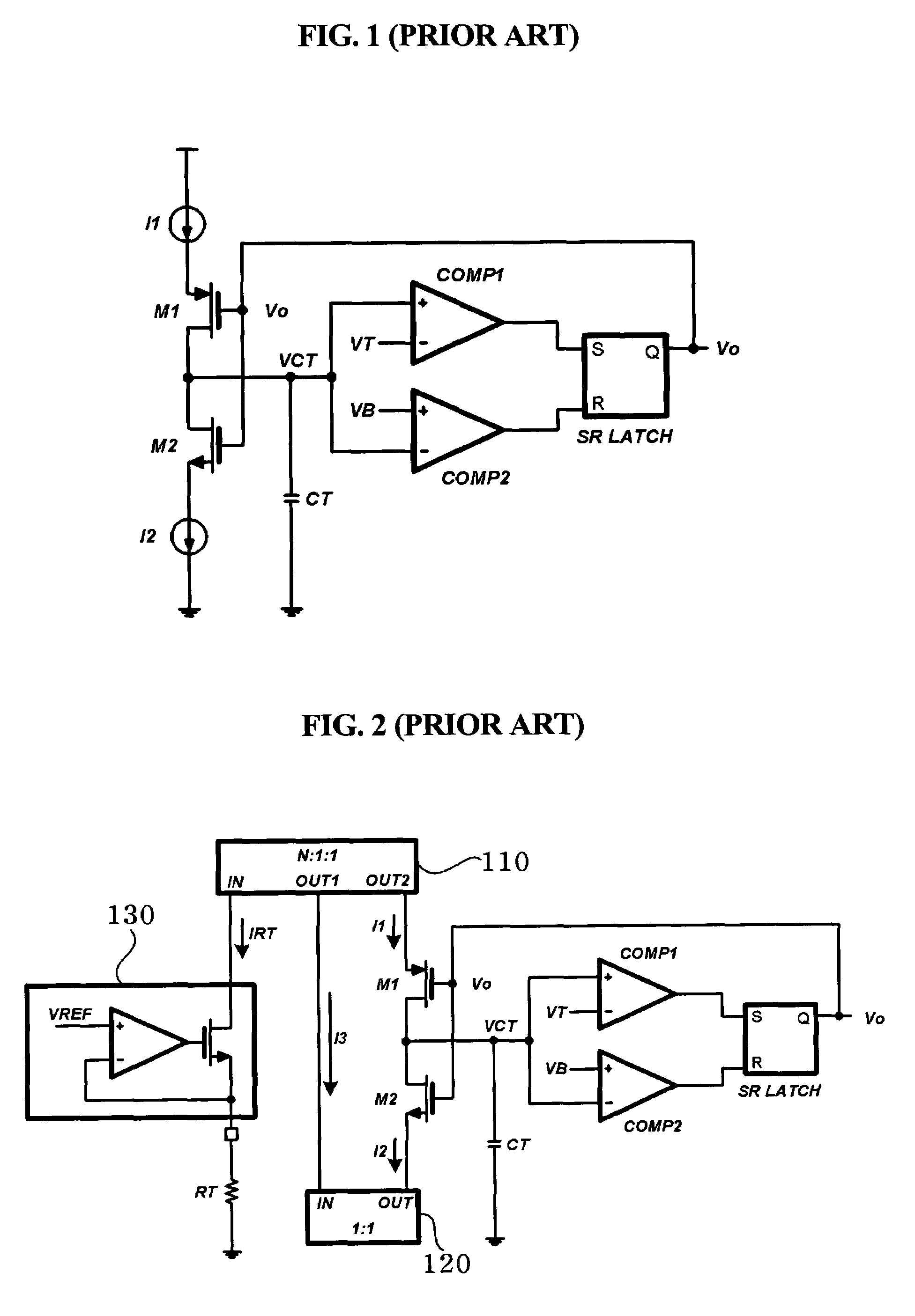
If the output voltage Vo assumes a low level, the above-mentioned operation is repeated, resulting in an oscillation.
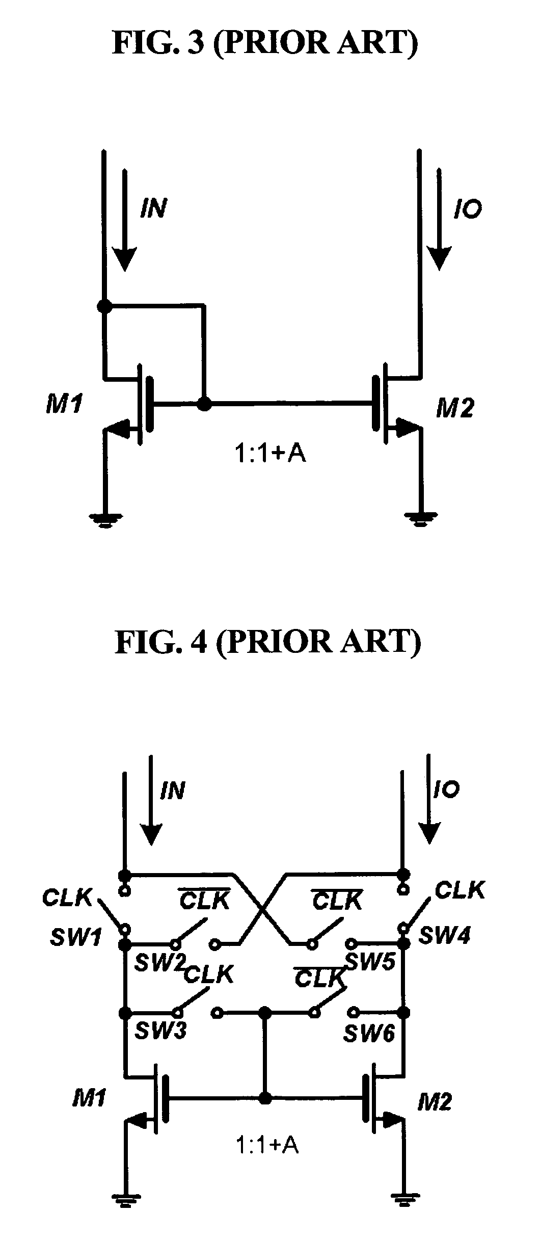
This is not an easy task, as the conventional current mirrors do not receive external clock signals.
For this reason, implementing the capacitor CT with high capacitance is not easy.
A low capacitance for capacitor CT, however, leads to an undesirably high frequency.
However, there are problems with the just-described approach.
The characteristics-mismatch of elements of the current mirror is such a problem.
Also, there may be a mismatch-dispersion, making it impossible to correctly generate a desired current signal lower than that of the apparent N-fold increased capacitor.

Method used


Image

  • RC oscillator integrated circuit including capacitor
  • RC oscillator integrated circuit including capacitor
  • RC oscillator integrated circuit including capacitor

Examples


Embodiment Construction

[0046]Embodiments of the present invention will be described in detail with reference to the annexed drawings. In the drawings, the same or similar elements are denoted by the same reference numerals. In the following detailed description of known functions and configurations incorporated herein will be omitted for clarity.

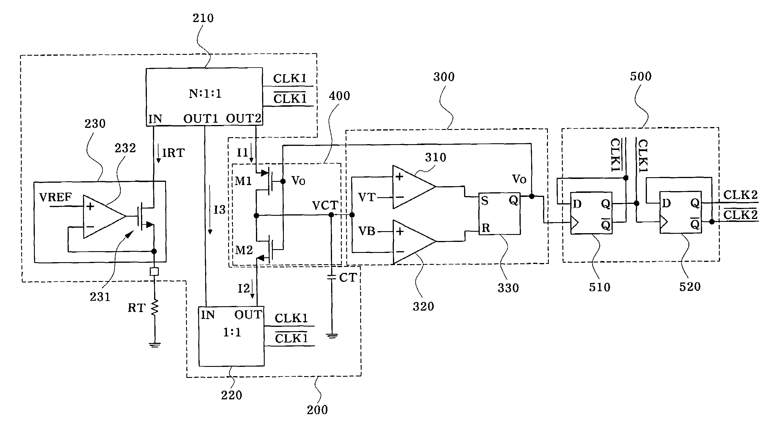
[0047]FIG. 7 is a circuit diagram illustrating an RC oscillator IC including a capacitor according to the present invention. The RC oscillator IC may include an active current mirror 200, an oscillation circuit 300, a feedback switching circuit 400, and a divider 500.

[0048]The active current mirror 200 is connected to an external resistor RT, receives a current signal IRT corresponding to a voltage signal applied to the resistor RT, performs 1 / N-times division of the received current signal IRT according to an input clock signal CLK1, and outputs a 1 / N-times current signal I1.

[0049]The oscillation circuit 300 generates an output voltage VCT corresponding to a char...


PUM


Abstract

An RC oscillator integrated circuit includes: an active current mirror connected to an external resistor, for receiving a current signal corresponding to a voltage signal applied to the external resistor, performing 1 / N-times division of the received current signal according to an input clock signal, and generating a 1 / N-times current signal; an oscillation circuit for generating an output voltage corresponding to a charging- or discharging-operation of a capacitor via a current path formed by the active current mirror; a feedback switching circuit for controlling a charging- or discharging-path of the capacitor by a feedback of an output signal Vo of the oscillation circuit; and a divider for generating not only a first clock signal capable of driving the active current mirror according to the output signal of the oscillation circuit, but also a second output clock signal having a compensated mismatch of the active current mirror.

Description

CROSS-REFERENCE TO RELATED PATENT APPLICATIONS[0001]This application claims the benefit of Korean Patent Application No. 10-2005-117246, filed on Dec. 2, 2005, in the Korean Intellectual Property Office, the disclosure of which is incorporated herein in its entirety by reference.BACKGROUND OF THE INVENTION[0002]1. Field of the Invention[0003]The present invention relates to an oscillator integrated circuit (IC), and more particularly to an RC oscillator IC including a capacitor.[0004]2. Description of the Related Art[0005]FIG. 1 is a circuit diagram illustrating a conventional saw-tooth oscillator (also called a triangular oscillator). Conventional saw-tooth oscillators include first and second transistors M1 and M2, a capacitor CT, first and second comparators COMP1 and COMP2, and an RS flip-flop SR LATCH. The RS flip-flop includes an output terminal Q, such that the Q output terminal generates a saw-tooth wave signal as an output voltage Vo. If the output voltage Vo assumes a low ...

Claims


Application Information

Patent Timeline
Patent Type & Authority Patents(United States)
IPC IPC(8): H03K3/02
CPCH03K4/502H03B5/24
Inventor HWANG, JONG-TAEKIM, DAE-HOJUNG, MOON-SANGKIM, DONG-HWAN
Owner SEMICON COMPONENTS IND LLC
Learn More