Multi-wavelength, multimode optical fibers

a multi-mode, optical fiber technology, applied in the field of optical fibers, can solve the problems of not actually identifying specific materials that have dispersive properties, difficult to achieve adequate bandwidth to meet customer specifications, and difficult to develop materials and processes capable of satisfying requisite specifications. , to achieve the effect of small change in dopt/d

Active Publication Date: 2008-09-02
FURAKAWA ELECTRIC NORTH AMERICA INC
View PDF17 Cites 64 Cited by
  • Summary
  • Abstract
  • Description
  • Claims
  • Application Information

AI Technical Summary

Problems solved by technology

Yet, in some cases, multimode fiber specifications are so stringent that it is difficult to develop materials and processes capable of satisfying requisite specifications.
With that limitation, it is sometimes difficult to achieve adequate bandwidth to meet customer specifications.
However, they did not actually identify specific materials that had those dispersive characteristics and that could be used to achieve the theoretical profile shapes.
While the importance of wavelength independence of optimum profile shape was well known in this period of time, the fiber core compositions that provided the appropriate dispersion were very few.
Moreover, the few suitable compositions were found to exhibit other problems, such as environmental sensitivity or manufacturing difficulty.
As a result, the B2O3—SiO2 glass system did not become the standard for multimode fiber production; the GeO2—SiO2 system did.
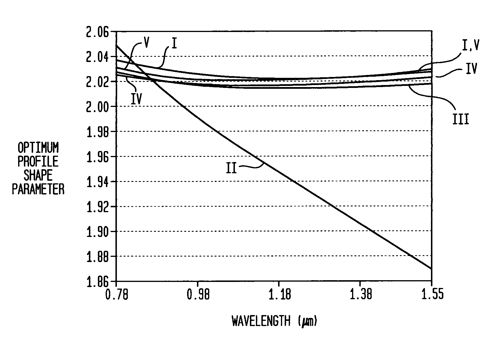
Cores that depend on GeO2 for refractive index profiling, however, do not exhibit the optimum profile shape for wavelength independence and can be optimized for only one transmission wavelength.

Method used


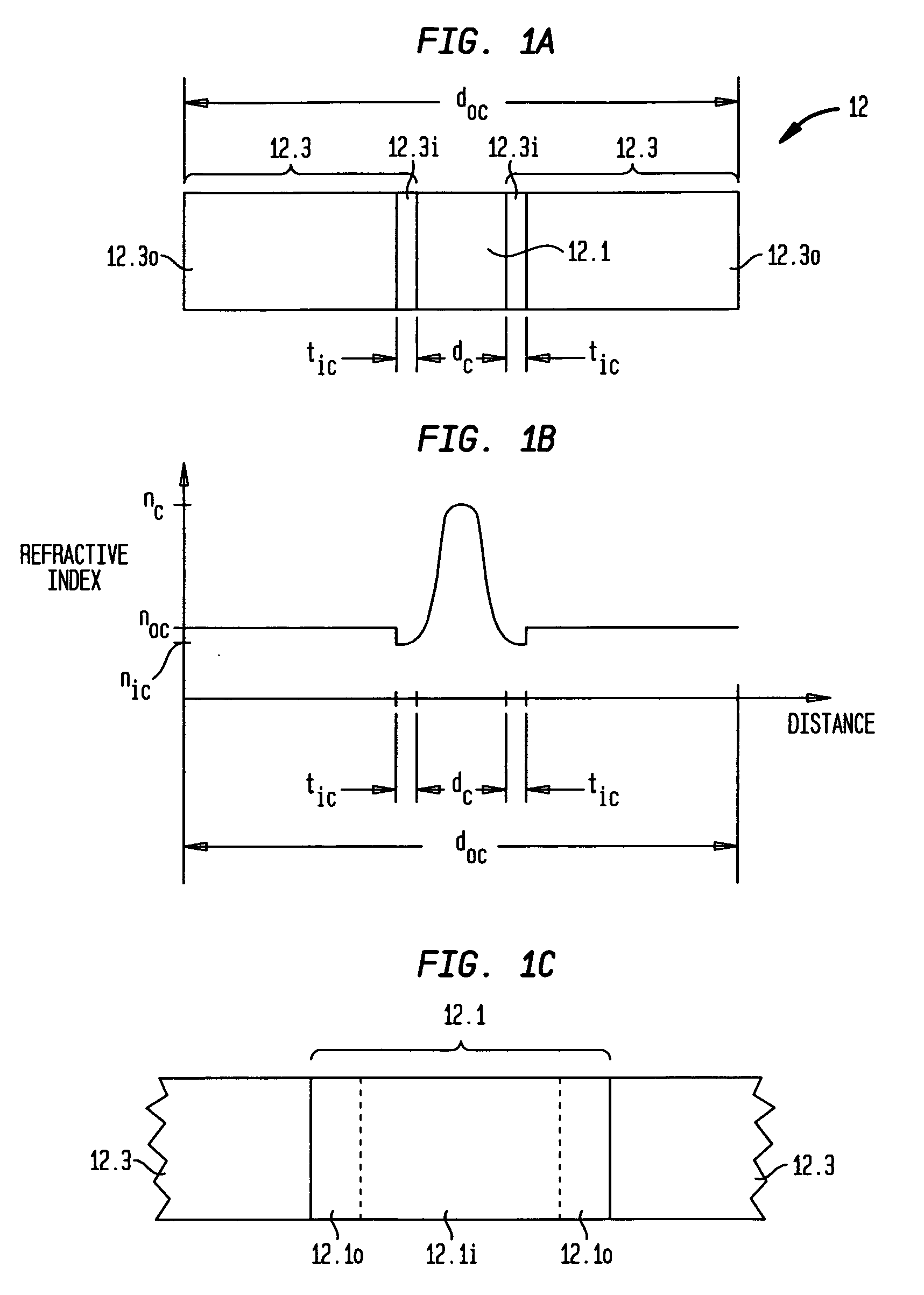
Image

  • Multi-wavelength, multimode optical fibers
  • Multi-wavelength, multimode optical fibers
  • Multi-wavelength, multimode optical fibers

Examples


Embodiment Construction

General Optical Fiber Fabrication

[0021]Optical fiber is produced from a glass preform that includes suitably doped regions from which the core and cladding will be formed. The preform is generally arranged vertically in a draw tower such that a portion of the preform is lowered into a furnace region. The portion of the preform placed into the furnace region begins to soften, and the lower end of the preform forms what is known as the neck-down region, where glass flows from the original cross-sectional area of the preform to the desired cross-sectional area of the fiber. From the lower tip of this neck-down region, the optical fiber is drawn.

[0022]The optical fiber typically contains a high-purity silicate glass core optionally doped with a refractive index-raising element such as germanium, an optional inner cladding of high-purity silica glass optionally doped with a refractive index-lowering element such as fluorine, and an outer cladding of undoped silica glass. In some manufact...


PUM

PropertyMeasurementUnit
wavelengthsaaaaaaaaaa
refractive index profileaaaaaaaaaa
wavelength rangeaaaaaaaaaa

Abstract

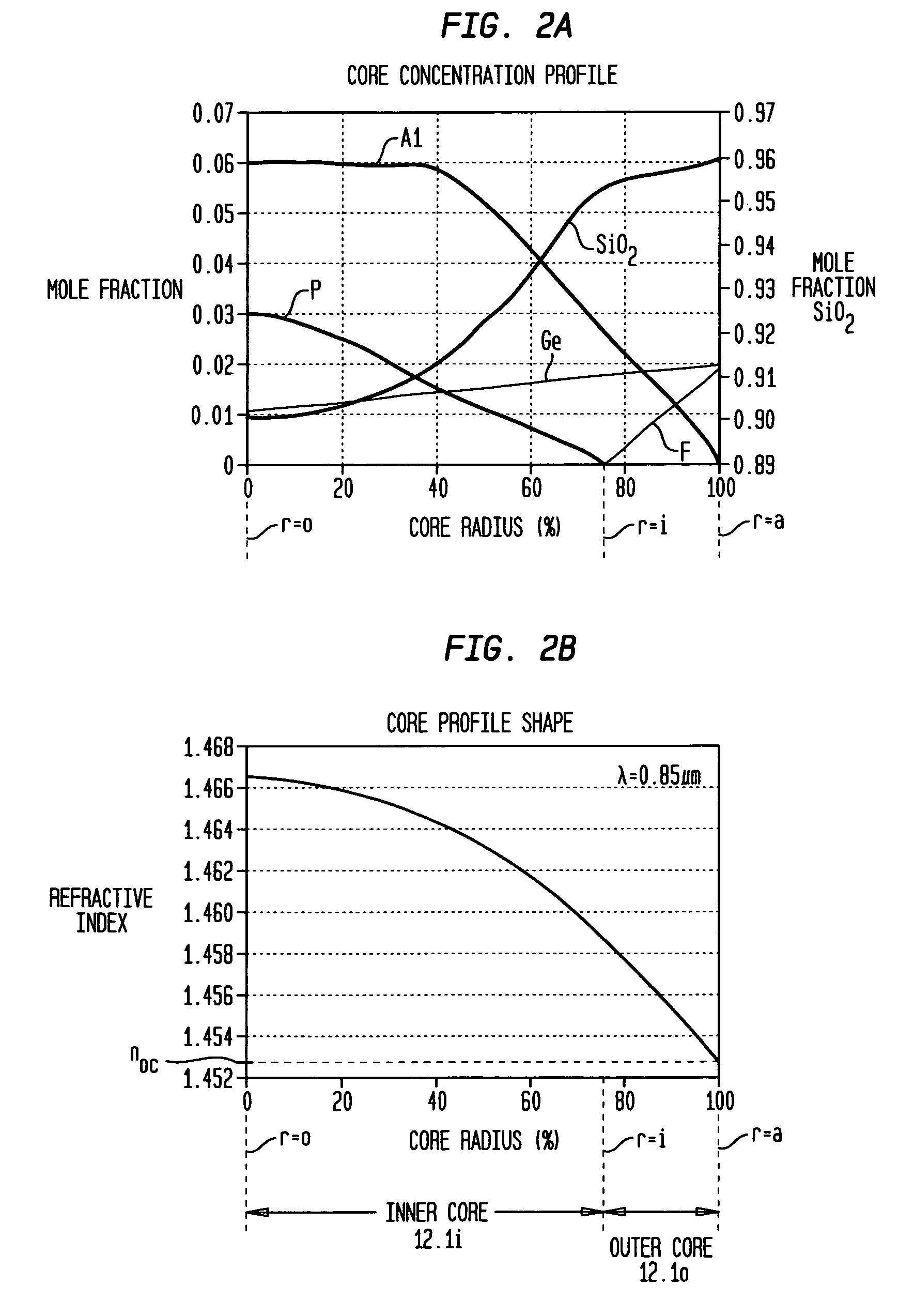
A silicate optical fiber comprises a graded index silicate core co-doped with aluminum oxide, phosphorus oxide, germanium oxide and fluorine in unique compositions that we have discovered allow multimode, multi-wavelength operation without significant intermodal dispersion. Illustratively, the core comprises a multiplicity of compositions whose refractive indices are graded from a maximum at or near the center of the core to a minimum at the interface with the cladding. Each core composition resides within a sub-volume of a 5 dimensional phase space in which an optimum core profile shape is essentially constant over the wavelength range of operation of the fiber. For operation in the wavelength range of about 0.78 μm to 1.55 μm, each composition preferably comprises no more than approximately 6 mole % Al2O3, 9 mole % P2O5, 6 mole % GeO2, 6 mole % F, and 90-100 mole % SiO2.

Description

BACKGROUND OF THE INVENTION[0001]1. Field of the Invention[0002]This invention relates to optical fibers and, more particularly, to multi-wavelength, multimode silica optical fibers.[0003]2. Discussion of the Related Art[0004]The manufacture of multi-transverse-mode optical fiber (simply multimode fiber hereinafter) has reached a very sophisticated level of development. Yet, in some cases, multimode fiber specifications are so stringent that it is difficult to develop materials and processes capable of satisfying requisite specifications. For example, the properties of many high bandwidth fibers, particularly their dispersion properties, are extremely sensitive to variations in the diameter of the fiber core and its refractive index profile. In fact, calculations for some commercially-available multimode fibers have shown that as little as a 1% variation in core profile induces up to a 10% variation in dispersion. Due to this dispersion effect, specifications for such fiber generall...

Claims


Application Information

Patent Timeline
Patent Type & Authority Patents(United States)
IPC IPC(8): G02B6/028
CPCG02B6/03627C03C13/046G02B6/0288C03B2201/12C03B2201/28C03B2201/31C03B2203/26C03B2201/32G02B6/00
Inventor FLEMING, JR., JAMES WILLIAMOULUNDSEN, III, GEORGE EDWARD
Owner FURAKAWA ELECTRIC NORTH AMERICA INC
Why Eureka
Try Eureka