Two-wire controlling and monitoring system for the irrigation of localized areas of soil
What is AI technical title?
AI technical title is built by Patsnap AI team. It summarizes the technical point description of the patent document.
a monitoring system and soil irrigation technology, applied in automatic controllers, valve types, applications, etc., can solve the problems of adding the total cost of two-wire irrigation systems for electronics, and achieve the effects of improving power transmission, improving corrosion resistance, and improving power transmission
Inactive Publication Date: 2008-09-02
S RAIN CONTROL
View PDF18 Cites 63 Cited by
Summary
Abstract
Description
Claims
Application Information
AI Technical Summary
This helps you quickly interpret patents by identifying the three key elements:
Problems solved by technology
Method used
Benefits of technology
Benefits of technology
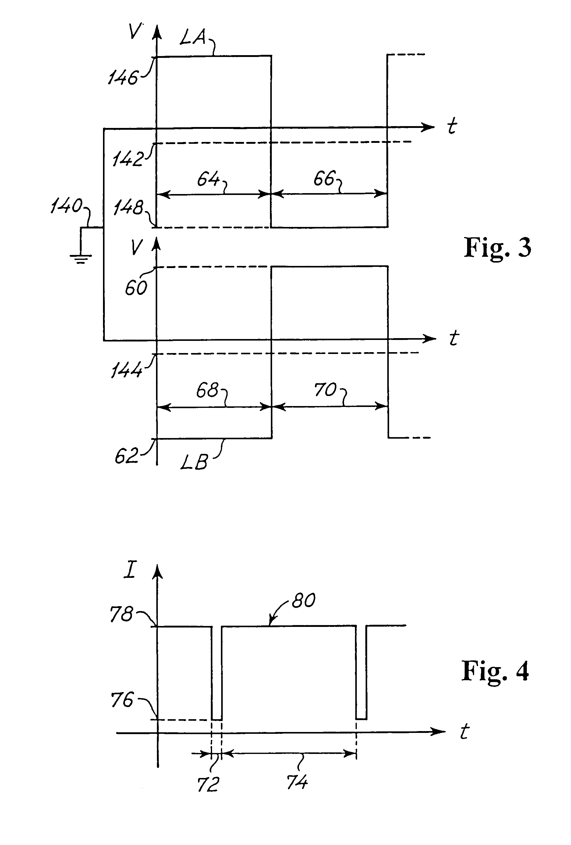
[0010]A particular advantage of the present invention is the utilization of a power supply signal for the operation of the controllable irrigation valves, hence performing an improved power transmission within general safety specifications.
[0011]A particular feature of the present invention is an improved corrosion resistance.
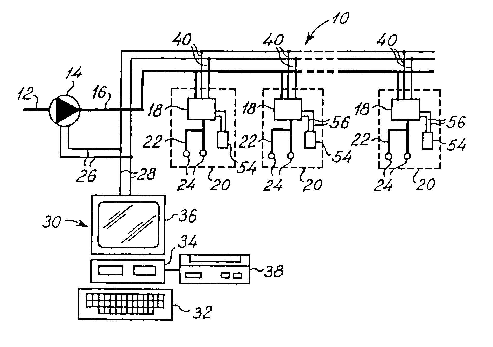
[0012]The above object, the above advantage and the above feature, together with numerous other objects, advantages and features, which will be evident from the below detailed description of a preferred embodiment of the present invention is, according to a first aspect of the present invention, obtained by a two-wire controlling and monitoring system particularly for irrigation of localized areas of soil and comprising:
[0013]a water pipeline providing water to said localized areas of soil,
[0014]a first plurality of controllable irrigation valves each positioned at a specific area of said localized areas of soil, communicating with said water pipeline, providing watering or non-watering of said specific area of said localized areas of soil and having a pair of valve control inputs,
[0015]a second plurality of field sensors positioned at specific areas of said localized areas of soil, providing specific irrigation parameters and having a pair of sensor outputs,
Problems solved by technology
Sinusoidal signals, being AC signals, generally need to be converted into DC in order to drive microprocessor electronic circuitry, adding total costs to the two-wire irrigation systems for the electronics incorporated in the remotely located irrigation valves or decoders.
Method used
Image
Click on the blue label to locate the original text in one second.
Reading with bidirectional positioning of images and text.
Examples
example
[0157]The sensor decoder 52 shown in FIG. 11 and as described above was implemented in a prototype version from the following components.
[0158]
FuseP1230 VResistors:R146R4R246R4R3100KR486K6R5100KR6100KR7100KR810KR9150KR10768KR1122K1R12100KR1339KR1439R2R1510KR1639KR1739KR1810KR1939KR2039KR2186K6R224R7R2310KR2410KR2510KR2610KR27470KR28470KR2956KR3039KR3127K1R3239KR3356KR34100KR352K49R36825RR372R2R3839KCapacitorsC11000μC210nC3100nC410μC533pC633pC71nC81nC9100nC10100nC111nC121nC131nDiodesD1DF04SD210 VD3BYD17DD4BYD17DD5BYD17DD6BYD17DD76V8D8LL4148D9LL4148D103V2D1122 VD1222 VD1315 VTransistorsQ1TIP122Q2BC856Q3BC846Q4BC856Q5BC846Q6MJD6039Q7MJD6039Integrated Circuits and CrystalIC1ST6220IC293C05IC3LM317LMIC4LM358NIC5LMC662CX16.144 MHz
[0159]The line decoder 44 shown in FIG. 12 and as described above was implemented in a prototype version from the following components.
PUM
Abstract
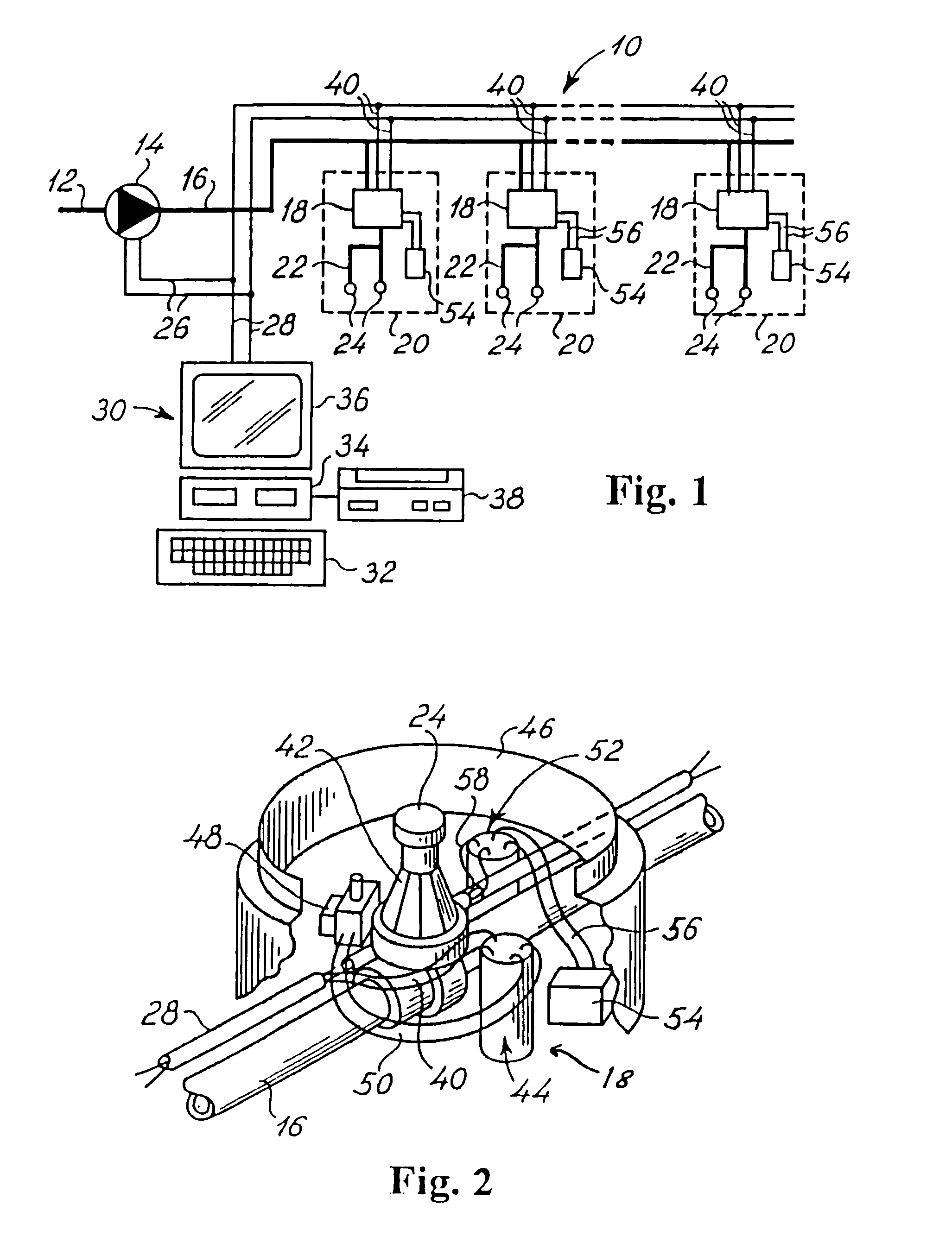
A controlling and monitoring system for irrigation of localized areas of soil includes a water pipeline, a plurality of controllable irrigation valves, a plurality of field sensors measuring specific irrigation parameters, and a plurality of localized irrigation control units. Each of the control units has a sensor decoder connected to a specific one of the field sensors and a line decoder connected to a specific one of the irrigation valves. The system further includes a controller and power supply unit that applies a first alternating DC voltage signal to a two-wire cable interconnecting the controller and power supply unit and the control units. The cable provides power from the controller and power supply unit to each of the control units. The controller and power supply unit transmits schedules of instructions to the control units, and receives the irrigation parameters from the control units, through the cable.
Description
CROSS-REFERENCE TO RELATED APPLICATIONS[0001]This application is a Continuation-in-Part of U.S. application Ser. No. 10 / 886,395, filed Jul. 7, 2004, now U.S. Pat. No. 6,993,416, which is a Continuation of U.S. application Ser. No. 09 / 721,461, filed Nov. 22, 2000, now U.S. Pat. No. 6,766,221, which is a Continuation of International Application No. PCT / DK00 / 00635, filed Nov. 15, 2000. The disclosures of these prior applications are incorporated herein by reference,FEDERALLY SPONSORED RESEARCH OR DEVELOPMENT[0002]Not ApplicableBACKGROUND OF THE INVENTION[0003]This invention relates generally a two-wire controlling and monitoring system particularly for irrigation of localized areas of soil.[0004]The most commonly known two-wire irrigation control systems, such as control systems described in U.S. Pat. Nos. 3,723,753, 4,004,612, 4,007,458, 4,131,882, 4,176,395, 4,535,401, 5,570,030 and 5,848,609 to which reference is made and which are hereby incorporated in the present specification b...
Claims
Application Information
Patent Timeline
Application Date:The date an application was filed.
Publication Date:The date a patent or application was officially published.
First Publication Date:The earliest publication date of a patent with the same application number.
Issue Date:Publication date of the patent grant document.
PCT Entry Date:The Entry date of PCT National Phase.
Estimated Expiry Date:The statutory expiry date of a patent right according to the Patent Law, and it is the longest term of protection that the patent right can achieve without the termination of the patent right due to other reasons(Term extension factor has been taken into account ).
Invalid Date:Actual expiry date is based on effective date or publication date of legal transaction data of invalid patent.

