Device for driving in rotation a toothed wheel, in particular a turntable

Active Publication Date: 2014-07-24
MICRO CONTROLE
View PDF4 Cites 10 Cited by
  • Summary
  • Abstract
  • Description
  • Claims
  • Application Information

AI Technical Summary

Benefits of technology

[0012]The aim of the present invention is to remedy these disadvantages. The invention relates to a device for driving in ro

Problems solved by technology

However, the pressure exerted on the flexible sleeve by this prestressing means is disrupted by the belt tension being exerted at the other extremity in such a way that the prestressing means cannot perform its f

Method used


Image

  • Device for driving in rotation a toothed wheel, in particular a turntable
  • Device for driving in rotation a toothed wheel, in particular a turntable
  • Device for driving in rotation a toothed wheel, in particular a turntable

Examples


Embodiment Construction

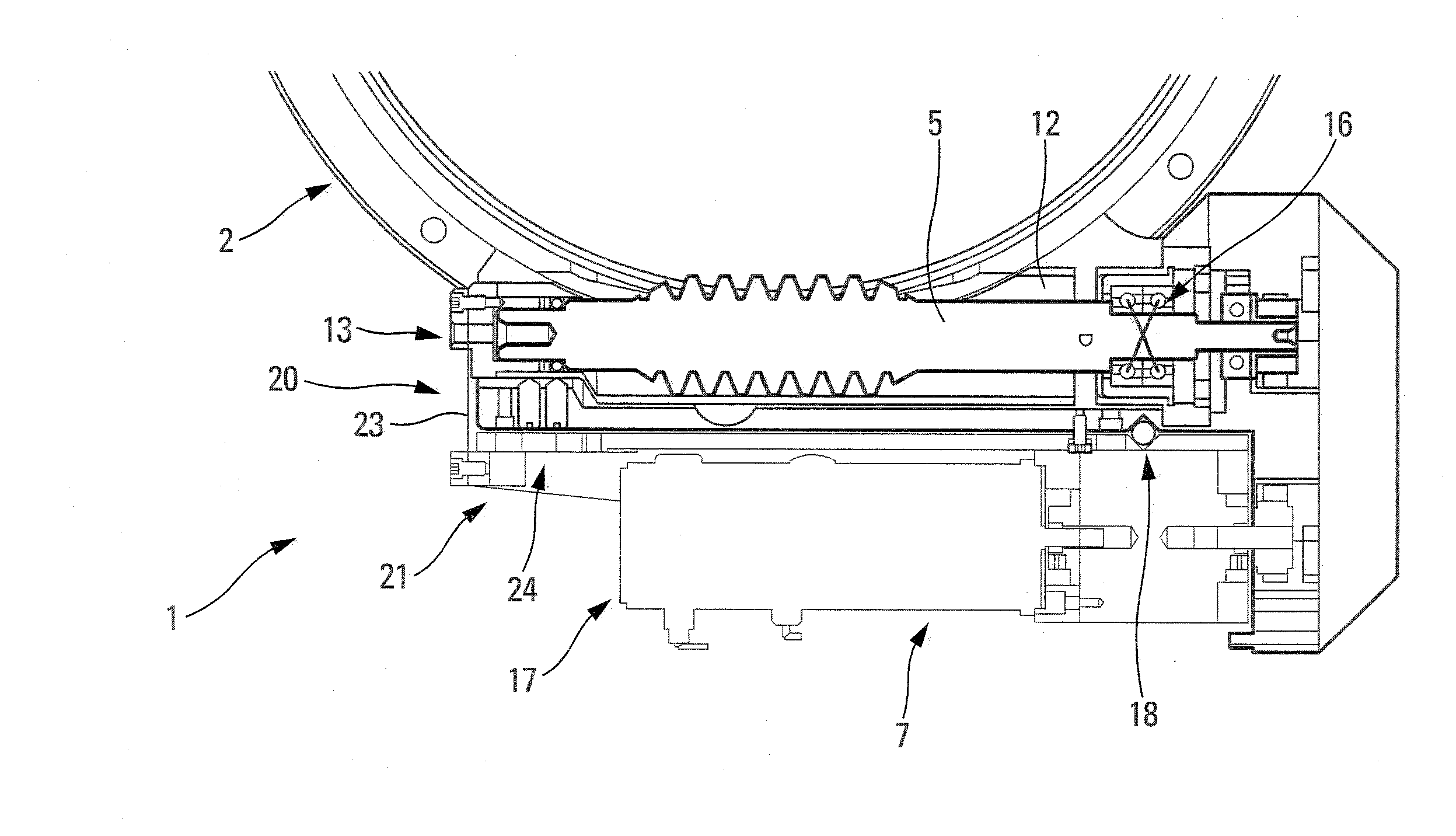
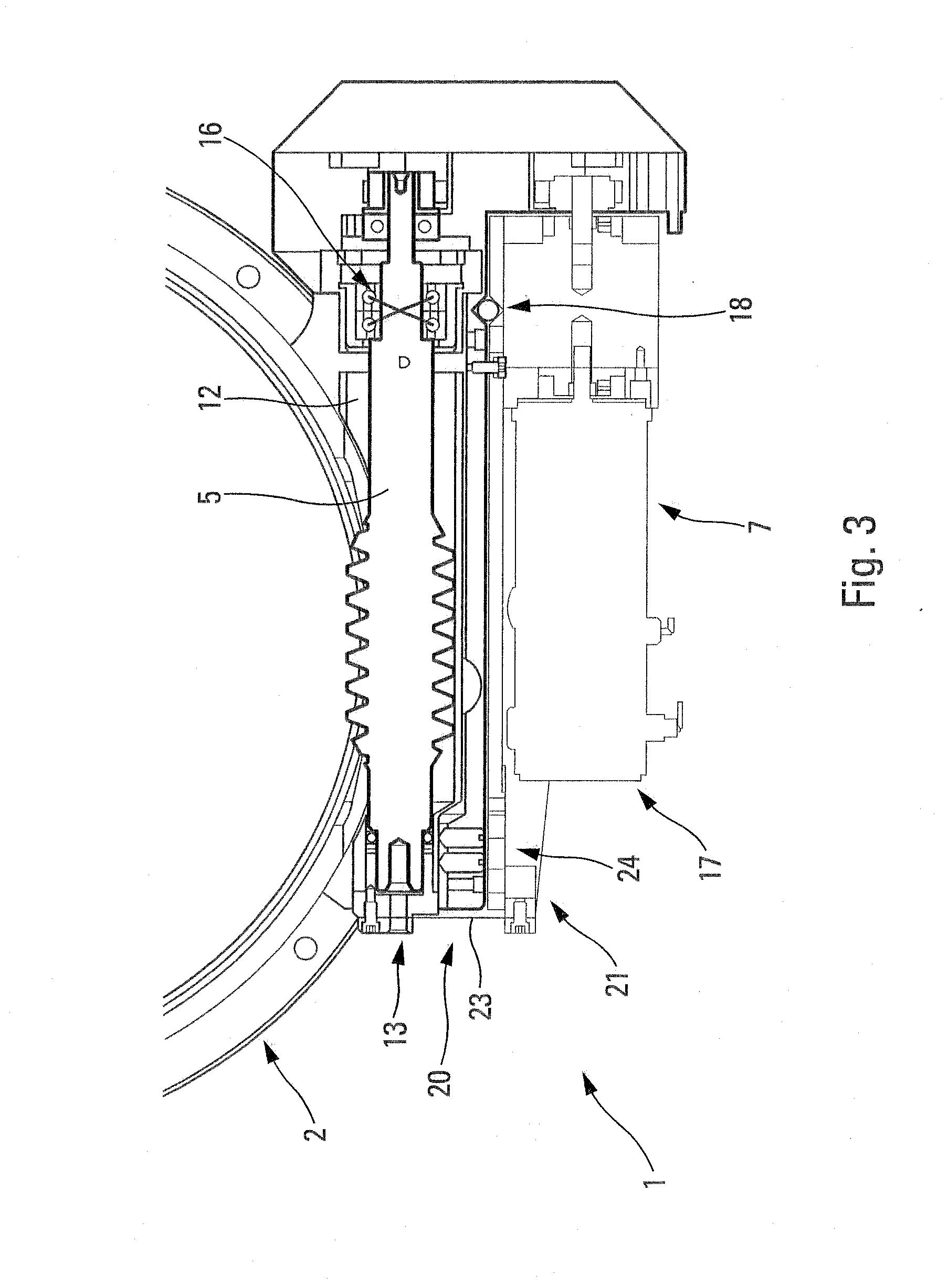
[0034]The present invention relates to a device 1 for driving in rotation a toothed wheel (or pinion) 2, forming in particular part of a motorised turntable or rotary plate (not shown). This turntable can be intended, in particular, for precision positioning applications (inspection of semiconductor wafers, metrology, positioning of components, microrobotics, etc.) in different fields, including research, industry, and defence.

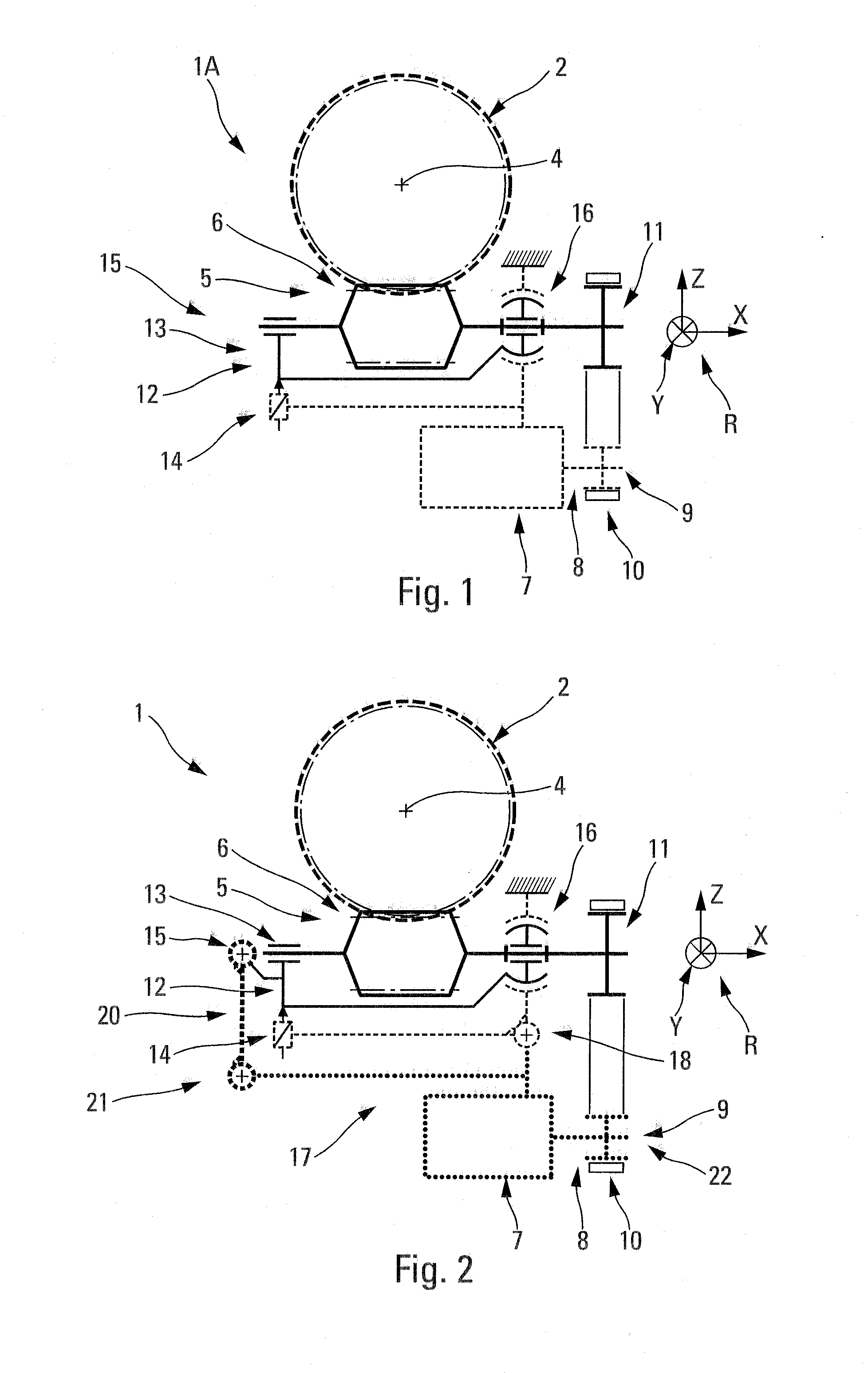
[0035]The toothed wheel 2 is driven in rotation around an axis 4 parallel to a direction Y (of a direction reference marker R).

[0036]A device for driving a toothed wheel in rotation, according to a standard embodiment 1A, has, as shown diagrammatically in FIG. 1, a worm 5 which is represented by a cylinder with a helical groove. This worm 5 is intended to mesh with the toothed wheel 2 at a zone 6, so that, in position, the longitudinal axis of the worm 5 is positioned at a tangent relative to the wheel 2 along a direction X.

[0037]Associated with this toothed w...


PUM


Abstract

A driving device for driving in rotation a toothed wheel, in particular a turntable, has a worm intended to mesh with the toothed wheel, a motor to drive the worm in rotation, a flexible sleeve that partially surrounds the worm in such a way as to form an assembly described as a worm/sleeve assembly, and a pre-stressing unit. The motor is arranged in a structure that is fitted pivotably relative to the worm/sleeve assembly, and the driving device also has a force transfer unit connecting the motor to the sleeve at a second extremity of the worm.

Description

CROSS REFERENCE TO RELATED APPLICATION(S)[0001]This application is based on French Application No. 1350622 filed Jan. 24, 2013, the entire contents of is incorporated by reference herein.FIELD [0002]The present invention relates to a device for driving in rotation a toothed wheel, in particular a turntable.BACKGROUND[0003]More particularly, although not exclusively, the present invention is applicable to a turntable or rotary plate that is intended for precision positioning applications (such as inspection of semiconductor wafers, metrology, positioning of components, and microrobotics) in different fields, including research, industry, and defence.[0004]Generally, a device of this kind for driving in rotation a toothed wheel usually includes the following:[0005]a worm that is designed to mesh with said toothed wheel; and[0006]a motor, a drive shaft of which is connected, via a belt, to a first extremity of said worm in order to drive the worm in rotation. In addition, this motor is...

Claims


Application Information

Patent Timeline
IPC IPC(8): F16H1/16
CPCF16H1/16Y10T74/19828G01R31/2887F16H2057/127F16H37/02F16H2057/0222F16H2057/0213F16H7/02
Inventor DURAND, ERICRETY, BRUNO
Owner MICRO CONTROLE
Why Eureka
Try Eureka