Transmission system and a method for control thereof

a transmission system and transmission system technology, applied in the direction of dc-ac conversion without reversal, electric power transfer ac network, emergency protective circuit arrangement, etc., can solve the problems of power transmission through the system falling to zero, large disturbance, severe consequences, etc., and achieve the effect of minimizing disturban

Active Publication Date: 2012-10-30
ABB POWER GRIDS SWITZERLAND AG
View PDF12 Cites 12 Cited by
  • Summary
  • Abstract
  • Description
  • Claims
  • Application Information

AI Technical Summary

Benefits of technology

[0007]The object of the present invention is to provide a transmission system of the type defined in the introduction and a method for control thereof, which make it possible to control the start and stop of a converter that minimizes the disturbance on a power transmission of said transmission system.
[0009]This way of using the control angle of said converters results in a smooth start and stop sequence of a said converter. By, controlling the converter in this way said DC by-pass breaker can be opened or closed in a reliable and safe way independent of the actual operation condition of the HVDC transmission system. “High delay angle” has different meaning depending upon the type of operation of the converter and an angle above 45° may sometimes be enough for being considered as high, while an angle above 140° may in another type of operation be required for being considered to be high.
[0011]According to another embodiment of the invention each said station has more than two said converters connected in series between said neutral bus and said pole, and said control devices of each station are adapted to increase or reduce the power transmitted between the stations by starting or stopping the operation of one converter of that converter station at a time. This results in a reliable and safe procedure to increase or reduce the power transmitted between the stations.
[0013]a control device belonging to a converter, called starting converter, in said rectifier being inactive is adapted to deblock said converter by starting to control it at high delay angle and gradually decreasing the delay angle until substantially all the DC current flows through that converter and then to control the by-pass breaker in parallel therewith to open at substantially zero current, the control device belonging to an inactive converter of the inverter is adapted to then deblock said converter by starting to control it at high delay angle and gradually decreasing the delay angle until substantially all the DC-current flows through that converter and to then open the by-pass breaker in parallel therewith at substantially zero current, and said arrangement is adapted to then control said starting converter to increase the voltage between the neutral bus and the pole to a voltage corresponding to the increased number of converters in operation. Such a system enables a smooth and by that reliable and safe procedure to increase the power transmitted between the converter stations.
[0014]According to another embodiment of the invention said control devices of said converters are co-ordinated for reducing the power transmitted between the stations at a substantially constant direct current flow in said transmission line by reducing the voltage between said neutral bus and said pole as follows: a control device belonging to a converter in said inverter station is adapted to control that converter at a gradually increasing delay angle until the voltage across this converter is close to zero, to then block the converter by firing a by-pass pair thereof and to then close the by-pass breaker in parallel with that converter, the control devices of the converters of the rectifier station are adapted to then compensate for the voltage drop between said pole and neutral bus by increasing the delay angle at which these converters are controlled, a control device belonging to a converter of the rectifier station is adapted to then control said converter at a gradually increasing delay angle until the voltage across this converter is close to zero, to then control the converter to be blocked by firing a by-pass pair thereof and to then close said by-pass breaker for taking over all the DC current. Such a system enables a smooth and by that reliable and safe procedure to reduce the power transmitted between the stations of the system.

Problems solved by technology

It may cause large disturbances with very severe consequences on AC systems connected to a said HVDC transmission system if all the converters of a converter station and by that a converter station would fail and by that the power transmitted through the system falls to zero.
Such a starting procedure or stop procedure of converters for either increasing or reducing the voltage between said neutral bus and said pole has in transmission systems of the type defined in the introduction so far been carried out in a rather abrupt way resulting in a considerable risk of causing disturbances in the high power transmission system and by that also in AC systems connected thereto.
This is particularly severe if the voltage and thereby the power is very high, such as in the case of a voltage above 600 kV, especially in the order of 800 kV or higher.

Method used


Image

  • Transmission system and a method for control thereof
  • Transmission system and a method for control thereof
  • Transmission system and a method for control thereof

Examples


Embodiment Construction

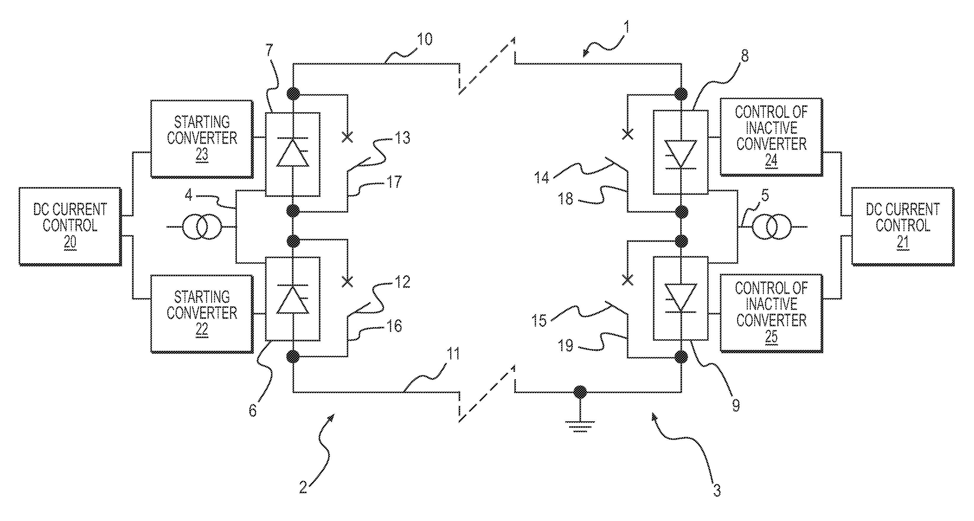
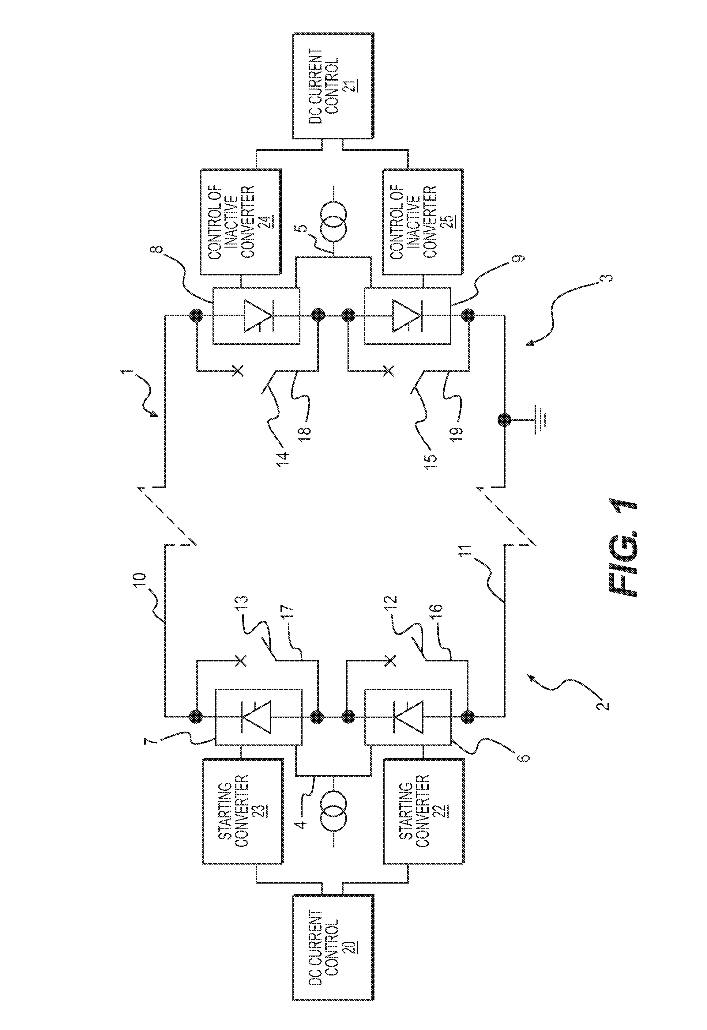
[0024]An HVDC transmission system according to a first embodiment of the invention is shown in FIG. 1. This system has here at each end of a transmission line 1 a converter station 2, 3 for connecting said transmission line to an AC system 4, 5 schematically indicated. The AC system 4 is assumed to be a generating system in the form of any type of power plant with generators of electricity, whereas the AC system 5 is assumed to be a consuming system or network connecting to consumers of electric power, such as industries and communities. Thus, a first converter station 2 is adapted to operate as rectifier and the other, second converter station 3 as inverter. Each station comprises a series connection of two converters 6, 7 and 8, 9 having a DC side thereof connected on one hand to a pole 10 of positive polarity of said transmission line on high potential and on the other to a neutral bus 11 on zero potential by being earthed. Each converter includes a number of converter valves in ...


PUM


Abstract

An HVDC transmission system including a rectifier station and an inverter station each having a series connection of at least two converters. A by-pass DC breaker is connected in parallel with each converter. A control device is adapted to deblock a blocked converter by starting to control the converter at high delay angle and gradually decreasing the delay angle until substantially all DC current flows through the converter and to then control the by-pass breaker to open at substantially zero current, and to stop the operation of a converter by controlling the converter at gradually increasing delay angle until the voltage across the converter is substantially zero and to then control the converter to be blocked by firing a by-pass pair thereof and to then control the by-pass breaker to close for taking over all the DC current when the voltage between a neutral bus and a pole of a transmission line between the stations is to be increased and reduced, respectively.

Description

CROSS-REFERENCE TO RELATED APPLICATIONS[0001]This application claims priority to U.S. provisional patent application 60 / 759,565 filed 18 Jan. 2006 and is the national phase under 35 U.S.C. §371 of PCT / SE2006 / 000718 filed 15 Jun. 2006.TECHNICAL FIELD OF THE INVENTION AND PRIOR ART[0002]The present invention relates to a HVDC (High Voltage Direct Current) transmission system comprising at each end of an HVDC transmission line a converter station for connecting said transmission line to an AC system, each said station comprising a series connection of at least two converters having a DC side thereof connected on one hand to a pole of said transmission line on high potential and on the other to a neutral bus on zero potential by being earthed, a first of said converter stations being adapted to operate as rectifier and the other, second as inverter, each converter having a by-pass DC breaker connected in parallel therewith in a current path forming a by-pass of said converter when said ...

Claims


Application Information

Patent Timeline
Patent Type & Authority Patents(United States)
IPC IPC(8): H02J3/36H02M5/45H02M7/10
CPCH02J3/36H02M7/7575Y02E60/60
Inventor BJORKLUND, HANSLUNGQVIST, ROLF
Owner ABB POWER GRIDS SWITZERLAND AG
Why Eureka
Try Eureka