Electric power steering device

a technology of power steering device and power steering face, which is applied in the direction of mechanical equipment, couplings, transportation and packaging, etc., can solve the problems of still having sufficient interference between power transmission faces, and achieve the effect of suppressing an increase in loss torque, convenient fixing, and easy adjustment of centering offs

Active Publication Date: 2007-07-12
JTEKT CORP
View PDF11 Cites 15 Cited by
  • Summary
  • Abstract
  • Description
  • Claims
  • Application Information

AI Technical Summary

Benefits of technology

[0010] According to this embodiment, the power transmission faces of the engagement arms include the relatively small interference power transmission faces, so that the elastic member can be easily fixed between the first and second engagement members. Further, the elastic member easily accommodates centering offset and angular offset between the first and second engagement members, and suppresses an increase in loss torque occurring due to the frictional resistance during the rotation, thereby improving the steering feeling.
[0011] In addition, even if the engagement arms of the elastic member are flattened during prolonged use, the relatively great interference power transmission faces still have sufficient interferences. Therefore, the torque transmission is mainly achieved through the power transmission faces still having the sufficient interferences. As a result, the noise and the torque transmission variation can be suppressed for a long period of time.

Problems solved by technology

In addition, even if the engagement arms of the elastic member are flattened during prolonged use, the relatively great interference power transmission faces still have sufficient interferences.

Method used


Image

  • Electric power steering device
  • Electric power steering device
  • Electric power steering device

Examples


Embodiment Construction

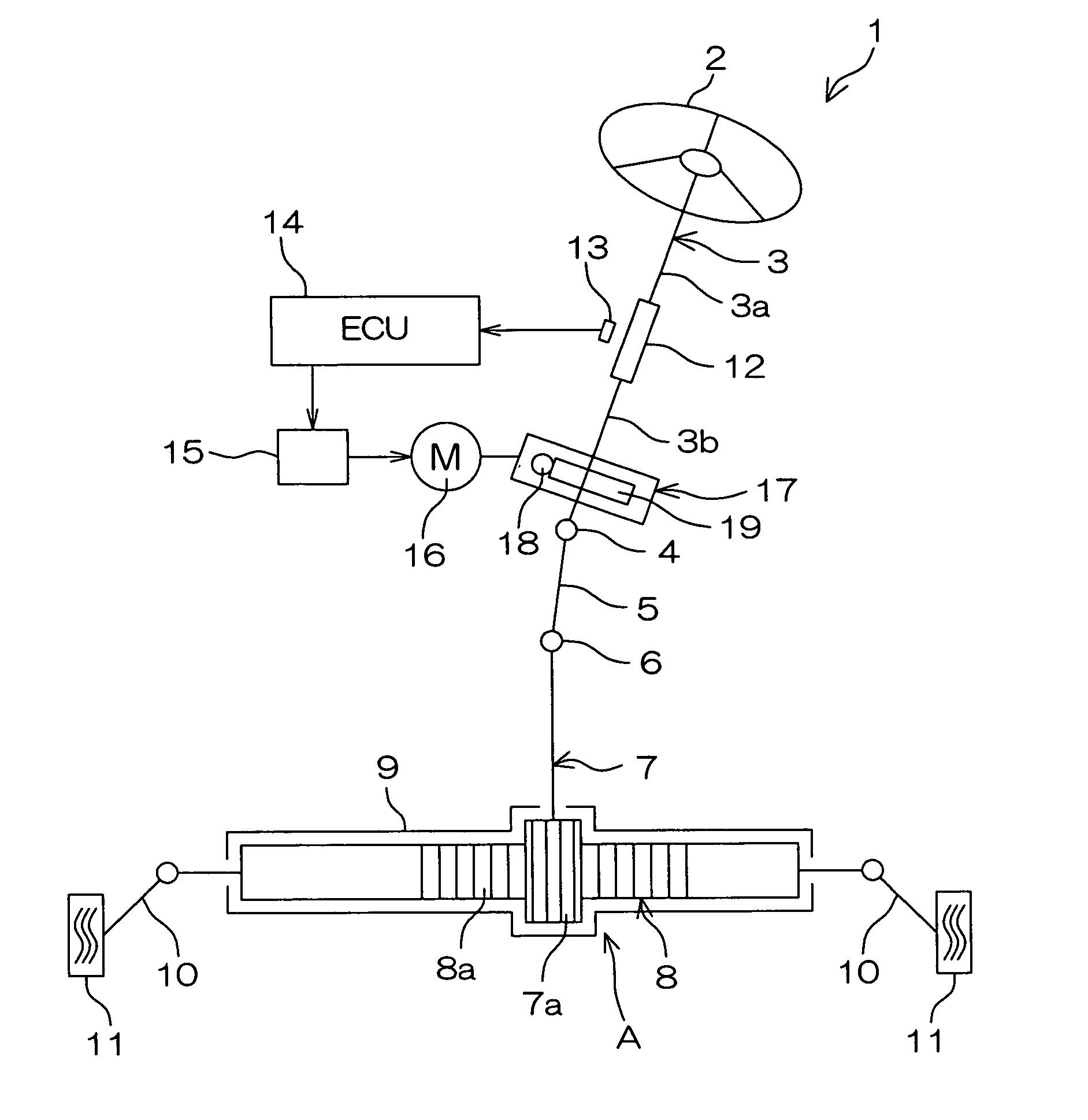
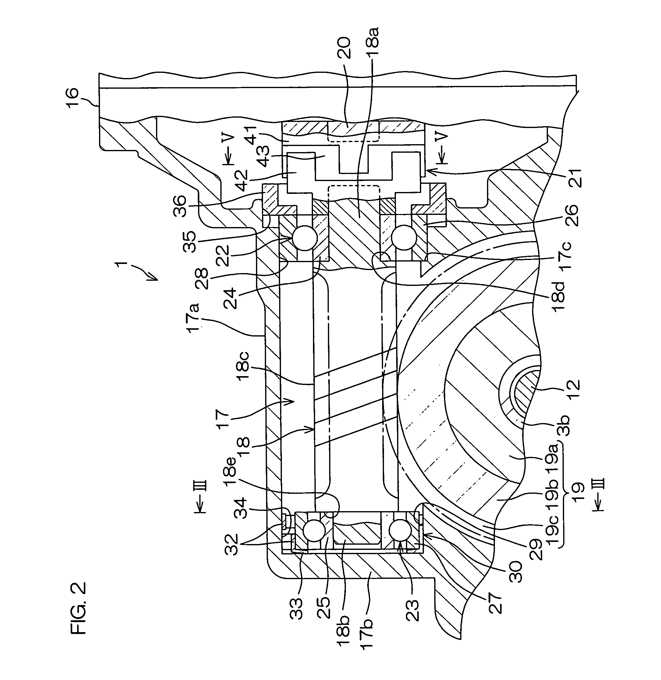
[0026] Embodiments of the present invention will hereinafter be described with reference to the attached drawings. FIG. 1 is a schematic diagram illustrating the construction of an electric power steering device including a power transmission joint according to one embodiment of the present invention.

[0027] Referring to FIG. 1, the electric power steering device 1 includes a steering shaft 3 connected to a steering member 2 such as a steering wheel, an intermediate shaft 5 connected to the steering shaft 3 via a universal joint 4, a pinion shaft 7 connected to the intermediate shaft 5 via a universal joint 6, and a rack bar 8 which has a rack tooth 8a meshed with a pinion tooth 7a provided around an end portion of the pinion shaft 7 and serves as a turning shaft extending transversely of a motor vehicle. The pinion shaft 7 and the rack bar 8 constitute a rack and pinion mechanism A as a steering mechanism.

[0028] The rack bar 8 is supported in a linearly reciprocal manner in a hous...


PUM


Abstract

An electric power steering device includes a power transmission joint (21) which coaxially couples an output shaft of a steering assist electric motor to an input shaft of a speed reduction mechanism for power transmission. The power transmission joint (21) includes first and second engagement members (41, 42) and an elastic member (43) disposed between the first and second engagement members (41, 42). The elastic member (43) includes an annular main body (44) and a plurality of engagement arms (45) provided at a predetermined interval circumferentially of the main body (44). The engagement arms (45) are engaged with engagement projections (55, 56) of the first and second engagement members (41, 42) circumferentially (X1) of the main body (44). Power transmission faces (46, 460) of the engagement arms (45) include power transmission faces (460) each having a relatively great interference (d1) and power transmission faces (46) each having a relatively small interference (d2).

Description

TECHNICAL FIELD [0001] The present invention relates to an electric power steering device which generates a steering assist force by an electric motor. BACKGROUND ART [0002] Automotive electric power steering devices (EPS) employ a speed reduction apparatus. A column-type electric power steering device, for example, is adapted to reduce the rotation speed of an output shaft of an electric motor through a worm shaft and a worm wheel to amplify the output of the electric motor and transmit the output to a steering mechanism, thereby providing torque assist for a steering operation. [0003] In general, a cylindrical joint which connects the output shaft of the electric motor to the worm shaft provides spline-coupling to an end of the worm shaft. The spline-coupled portion has a slight play defined in a rotation direction, so that noise occurs due to rattling attributable to the play. [0004] To cope with this, an electric power steering device is provided in which an output shaft of an e...

Claims


Application Information

Patent Timeline
Patent Type & Authority Applications(United States)
IPC IPC(8): B62D5/04F16D3/50F16D3/68
CPCF16D3/68B62D5/0409F16C27/04F16C23/08
Inventor IWASA, SOUICHIIIDA, TOSHIO
Owner JTEKT CORP
Why Eureka
Try Eureka