Support frame with articulating structures

a support frame and structure technology, applied in the field of support frames, can solve the problems of unfavorable mechanical performance of the actuator, unfavorable mechanical stability of the actuator, so as to reduce the potential for undesirable consequences, and reduce the effect of bending

Active Publication Date: 2008-09-09
GF HEALTH PRODS
View PDF3 Cites 14 Cited by
  • Summary
  • Abstract
  • Description
  • Claims
  • Application Information

AI Technical Summary

Benefits of technology

[0014]According to one advantage of the present invention, the articulating structures collapse to a compact orientation when the bed is lowered to a low position. Yet, the longitudinal axis of the actuator of the linear drive assembly is maintained at an angle relative to the plane of the frame that is substantially greater than zero. Because this angle does not approach zero, the cosine of this angle also does not approach zero. Accordingly, the vertical lift component of the actuator force never approaches zero, even when the bed is at the fully lowered position.
[0015]According to another advantage of the present invention, the geometry of the rigid support provides a mechanical advantage to the linear drive assembly. This is advantageously accomplished by having both ends of the linear drive assembly move in opposite directions relative to the frame during operation. The first end of the linear drive assembly applies a force to push the drag link from the first articulating structure towards the second articulating structure. The second end of the linear drive assembly applies force to the rigid member of the first articulating structure to cause the second end of the first articulating structure to rotate away from the frame. This rotation causes the first end of the rigid member of the articulating structure to apply a redirected force against the drag link to also force the drag link towards the second articulating structure.
[0016]Due to the described mechanical advantage achieved, there is no need for mechanical or hydraulic compressive assist mechanisms. Advantageously, elimination of the mechanical and hydraulic compressive assist mechanisms eliminates a potential for undesirable consequences that may occur as a result of the failure of the assist mechanisms.
[0017]Related, a single linear drive assembly can be used to raise the bed from a lowered position to a raised position. Using a single linear drive assembly and a drag link to simultaneously raise and lower two articulating structures eliminates the risk that two sides of the bed could move at different rates.
[0018]A still further advantage of the present invention is that the bed is raised from a low position to a high position with a relatively low amount of swing, or movement of the frame relative to the casters. Accordingly, the center of gravity of the bed is maintained at an acceptable point during the entire movement of the bed. Further, less space is required for operation of the bed.
[0019]A still further advantage yet of the present invention is that only two casters are needed at each end of the bed. This is accomplished by use of a serpentine support in each articulating structure. The serpentine supports, combined with the rigid support, the frame and the caster supports comprise a structure resembling a split parallelogram. In this regard, the casters can be oriented at a selected orientation with respect to the ground and the frame can be oriented parallel to the ground throughout the entire range of motion of the bed.

Problems solved by technology

The actuator is therefore at a mechanical disadvantage when the cosine of the angle approaches zero.
Such an approach can be undesirably expensive.
However, such components may fail unexpectedly.
In addition, when such mechanisms fail, time delay, damage or injury may occur.
Presently, to achieve a low bed position, one must also accept a mechanical disadvantage.
Further, elimination of the mechanical disadvantage requires that the cosine of the angle between the actuator and bed frame not approach zero, and accordingly that the bed not be lowered to the desired position.
A still further disadvantage yet of some existing angle adjustable beds that have two motors is that the motors can get out of synchronization.
This could jeopardize the health and safety of any person on the bed.
Further, such a drawback could make transport during raising and lowering of the bed impractical and hazardous.
A still further disadvantage yet of existing angle adjustable beds is that they may require an undesirably large amount of swing to reposition the bed from the lowered position to the raised position.
A large swing is disadvantageous for several reasons.
First, having bed frame move forward or rearward relative to the wheels changes the center of gravity of the bed.
Second, with the ever increasing pressure to reduce room size and to fit more items into existing rooms, there is a sizable disadvantage to a bed that requires a relatively large amount of swing to raise to the raised position.
A still further drawback yet is that some beds require three or more casters at each end of the bed to provide a stable structure.
This leads to an undesirable number of components.
These stabilizing rods can interfere with and limit the use of items such as over bed tables, patient lifts and the like.

Method used


Image

  • Support frame with articulating structures
  • Support frame with articulating structures
  • Support frame with articulating structures

Examples


Embodiment Construction

[0033]While the invention will be described in connection with referred embodiments, it will be understood that it is not intended to limit the invention to those embodiments. On the contrary, it is intended to cover all alternatives, modifications and equivalents as may be included within the spirit and scope of the invention as defined by the appended claims.

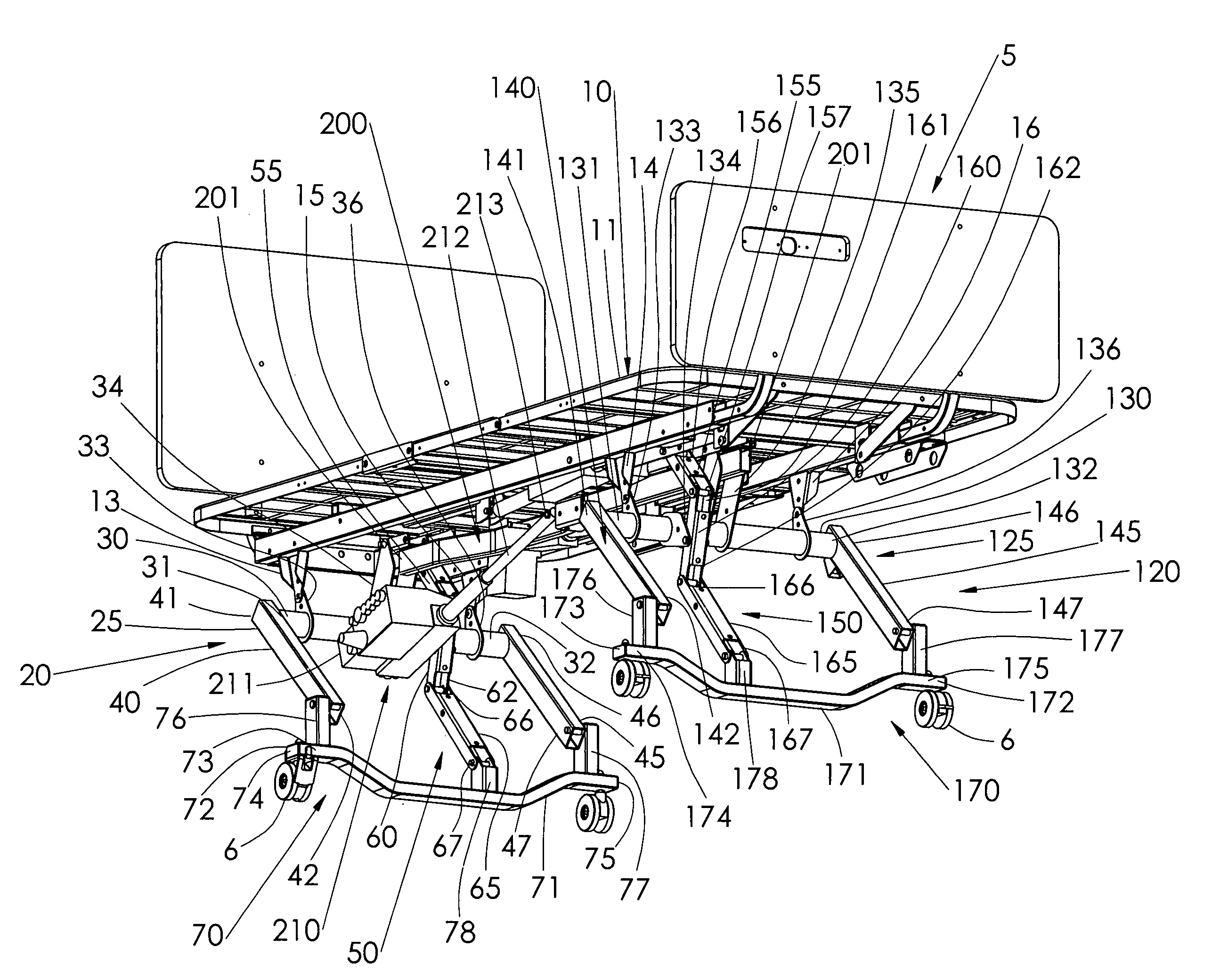
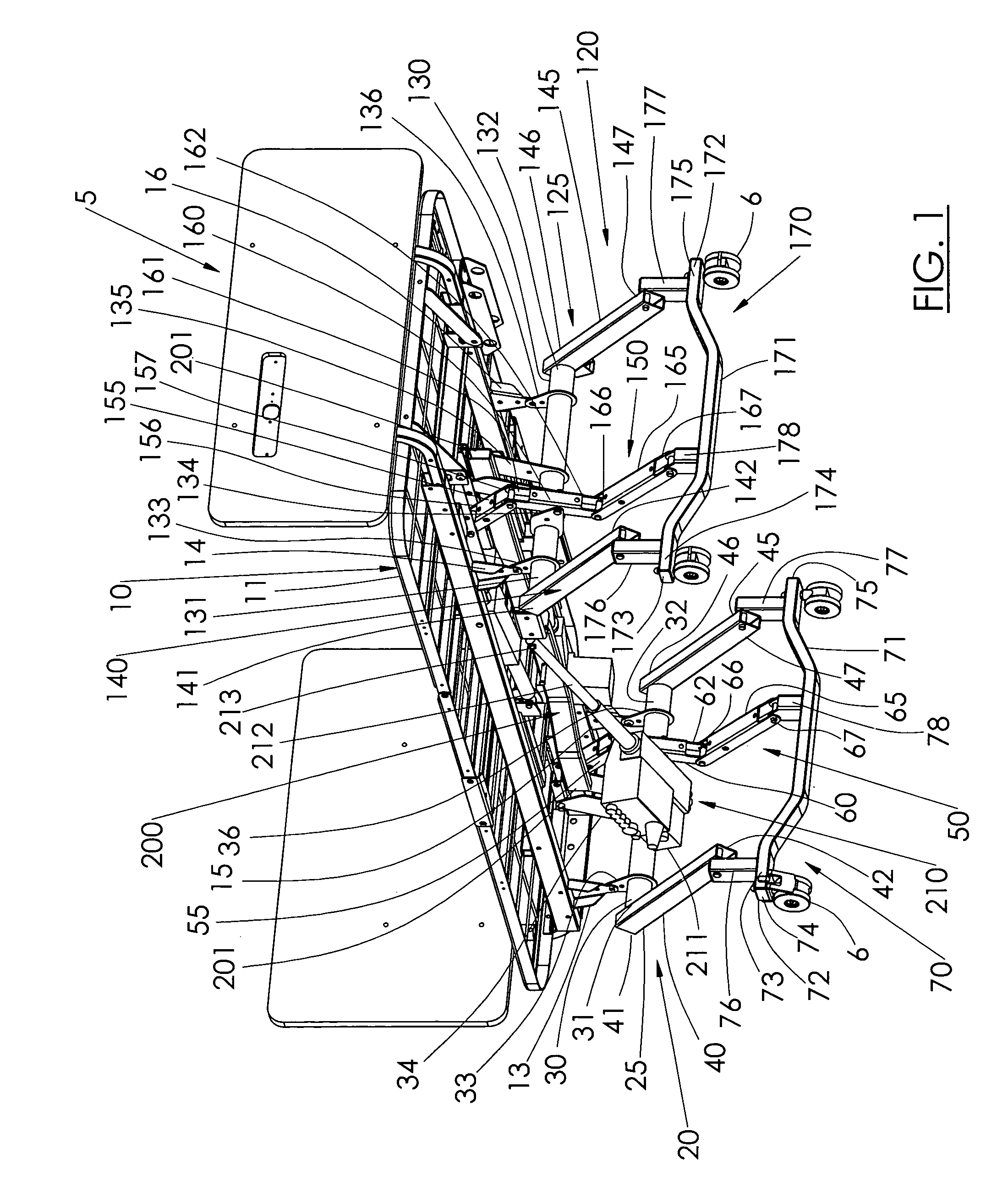
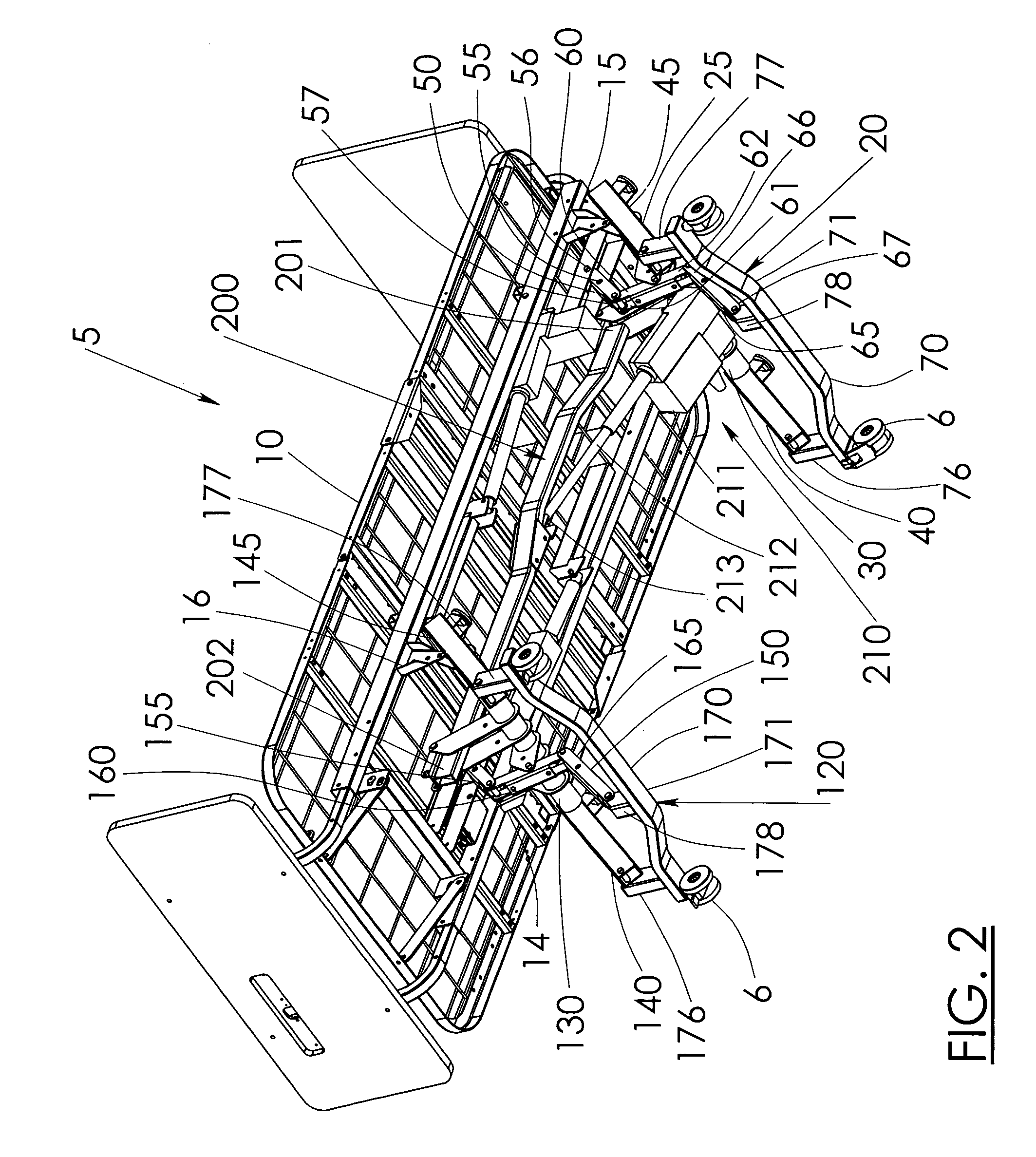
[0034]The preferred embodiments of the present invention are shown and described in relation with a bed 5 having four casters 6. The casters 6 of the bed 5 preferably rest on a floor 1 lying in a plane 2. In a preferred embodiment, the bed 5 has a frame 10, a first articulating structure 20, a second articulating structure 120, a drag link 200 and a linear drive assembly 210. The bed frame 10 is understood to include deck assemblies and the like, however, for the sake of clarity, the frame 10 will be described as a single structure. Of course, the principles of the present invention are applicable to beds having frames with di...


PUM


Abstract

The present invention has a frame, two articulating structures, a drag link and a linear drive assembly. Each articulating structure has a rigid support, a serpentine support and a caster support. The rigid supports are pivotally connected to the frame and to the caster supports. The serpentine supports are pivotally connected to the frame, the rigid support and the caster support. The drag link makes the first and second articulating structures cooperate. The linear drive assembly is connected to the rigid support of one articulating structure and to the drag link. The linear drive assembly causes the bed to rise by acting in two directions, one to directly push the drag link in a first direction and the second to redirect the linear drive assembly force to indirectly push the drag link in the first direction by rotating the first rigid structure away from the frame.

Description

[0001]This application claims priority on US Provisional Application having application No. 60 / 585,424, filed on Jul. 2, 2004, the entire disclosure of which is hereby incorporated herein by reference.BACKGROUND OF THE INVENTION[0002]1. Field of the Invention[0003]The present invention relates to a support frame, and more particularly to a vertically adjustable support frame that is selectably raised and lowered by extending and retracting at least one articulating structure.[0004]2. Description of the Related Art[0005]Typically, height and angle adjustable beds are used by medical institutions, such as hospitals and nursing homes. The beds usually include a bed frame and an articulating mechanism for lowering the bed frame to a low position and raising the bed frame to a high position so that it may be used as a gurney or at any height in between. As a result, a patient can be transferred by merely sliding the patient from one gurney to another or a chair.[0006]It is known to have ...

Claims


Application Information

Patent Timeline
Patent Type & Authority Patents(United States)
IPC IPC(8): A61G7/012
CPCA61G7/012A61G7/018
Inventor EDGERTON, JOHN
Owner GF HEALTH PRODS
Why Eureka
Try Eureka