Control device for servo die cushion

a technology of control device and die cushion, which is applied in the direction of program control, shape safety devices, instruments, etc., can solve the problems of difficult to increase the force gain for rapid acceleration or deceleration, vibration at a low frequency may occur in the machine,

Active Publication Date: 2008-09-09
FANUC LTD
View PDF13 Cites 7 Cited by
  • Summary
  • Abstract
  • Description
  • Claims
  • Application Information

AI Technical Summary

Benefits of technology

[0008]Therefore, an object of the present invention is to provide a control device, of a die cushion mechanism, by which the force between the slide and the die cushion may follow the commanded value even in the rapid acceleration or deceleration of the slide and, moreover, a problem such as vibration of the machine may be prevented in the gradual acceleration or deceleration of the slide.
[0012]Concretely, the correcting part may correct the commanded current value by adding an acceleration of the slide multiplied by a constant number to the commanded current value.

Problems solved by technology

On the other hand, when a force gain is increased for the rapid acceleration or deceleration of the slide, a problem such as vibration at a low frequency may occur in the machine during the gradual acceleration or deceleration of the slide.
Due to this, it is difficult to increase the force gain for rapid acceleration or deceleration.

Method used


Image

  • Control device for servo die cushion
  • Control device for servo die cushion
  • Control device for servo die cushion

Examples


first embodiment

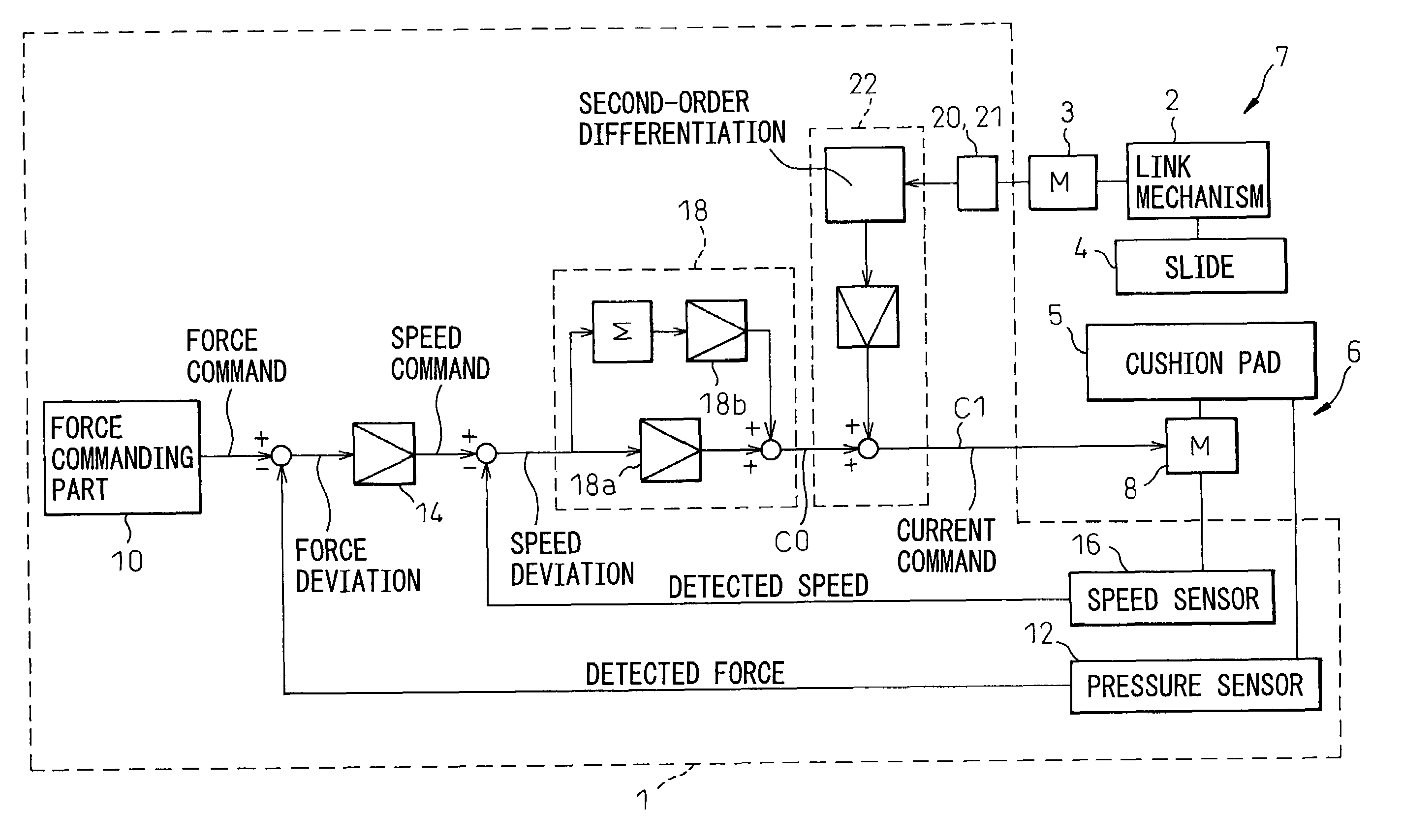
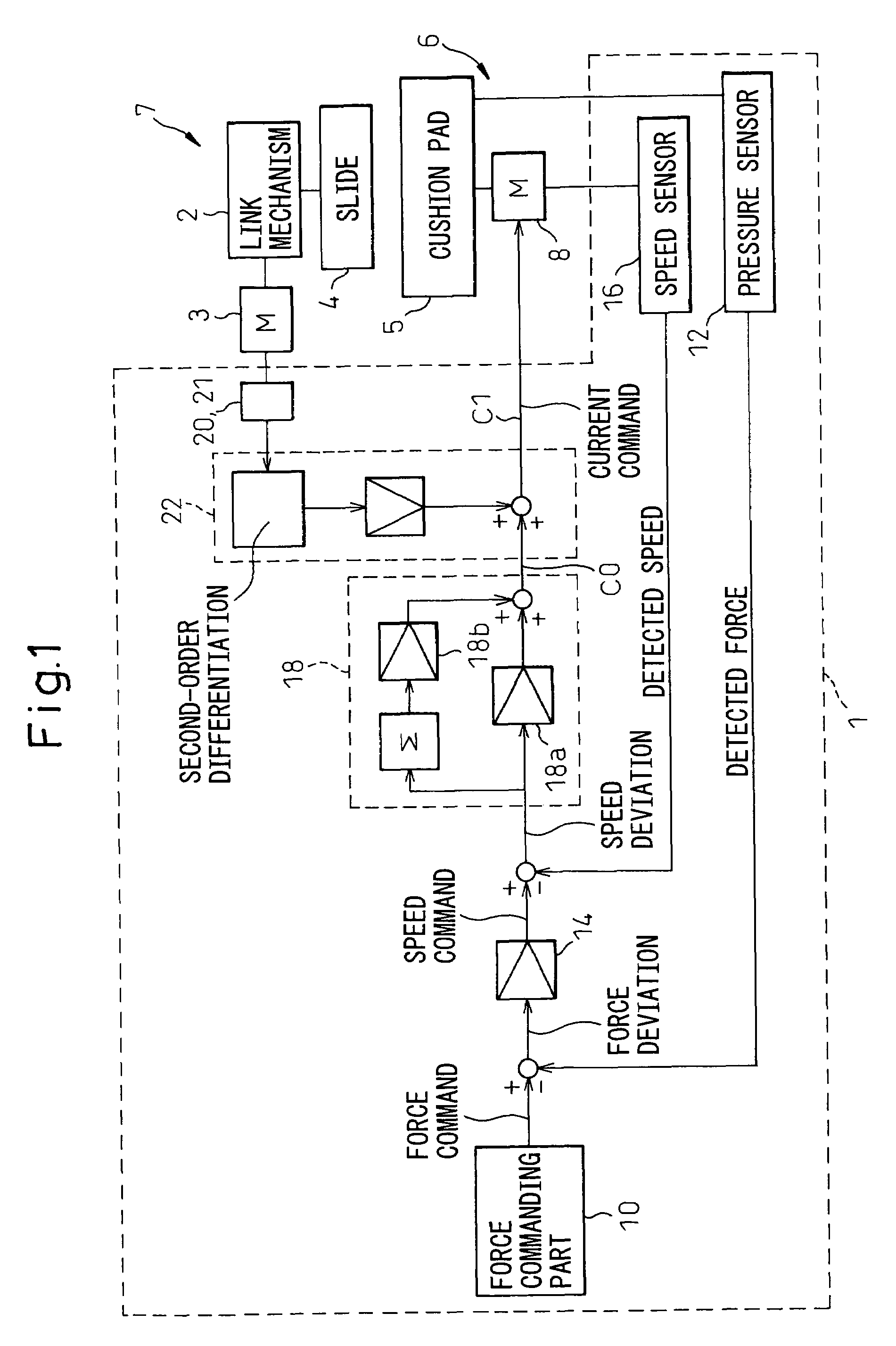
[0026]As shown in FIG. 1, a control device 1 according to the invention is used for a press machine 7 having a slide 4 driven by a servomotor 3 via a suitable link mechanism 2 and a die cushion mechanism 6 including a cushion pad 5 capable of moving corresponding to the motion of the slide 4. The control device controls a servomotor 8 for driving the cushion pad 5 so as to generate a predetermined force or pressure between the slide 4 and the cushion pad 5. As components other than the control device 1 may be the same as the conventional components, a detailed description of the components is omitted.

[0027]As shown in FIG. 1, the control device 1 of the first embodiment includes a force commanding part 10 for generating a force command including a commanded force value to be generated between the slide 4 and the die cushion mechanism 6, a force detecting part 12 such as a force sensor for detecting a force generated between the slide 4 and the die cushion mechanism 6, a speed comman...

second embodiment

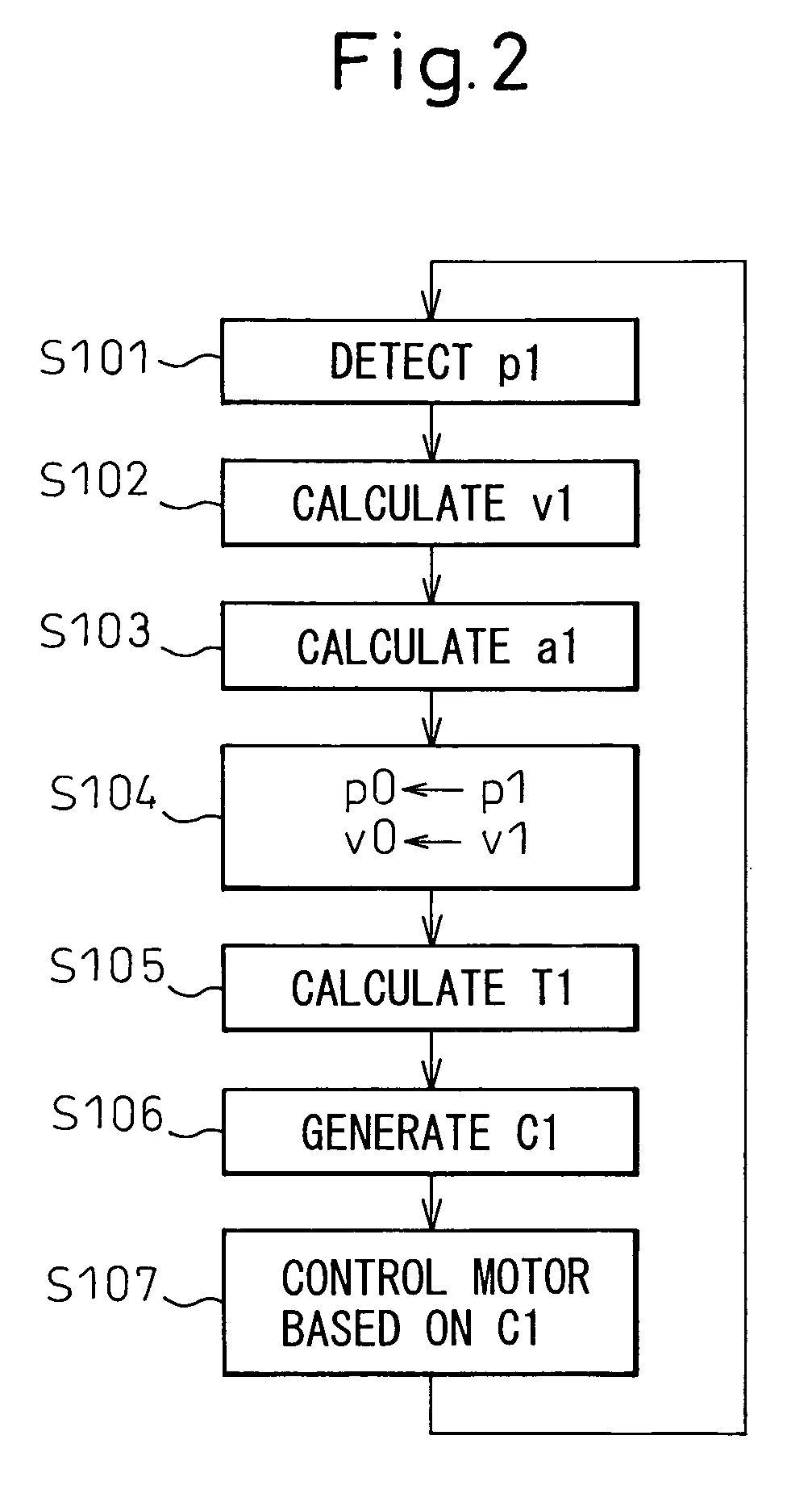
[0037]As described above, in the second embodiment, the correcting part 22′ corrects the force gain. In other words, steps S101′ to S104′ of FIG. 4 are the same as steps S101 to S104 of FIG. 2. However, in step S105′, a force gain Gp1 is calculated by using the above slide acceleration a1 and the following equation (4), instead of calculating the correction torque.

Gp1=k2·Gp0·a1  (4)

[0038]wherein k2 is a constant number and Gp0 is an initial force gain.

[0039]According to the prior art, in the speed commanding part 14, the speed command could be generated by multiplying a force gain Gp0 by a force deviation calculated by a differential between the commanded force value and the detected force value. However, in the present invention, a speed command V1 is generated and corrected by using a force gain Gp1 which can be varied corresponding to the acceleration of the slide (step S106′). Further, a current command C1′ is generated and corrected based on the speed command V1 (step S107′). T...

third embodiment

[0042]As shown in FIG. 7, in the third embodiment, the correcting part 22″ corrects the speed gain. In other words, steps S101″ to S104″ of FIG. 7 are the same as steps S101 to S104 of FIG. 2. However, in step S105″, a speed gain Gv1 is calculated by using the above slide acceleration a1 and a following equation (5).

Gv1=k3·Gv0·a1  (5)

[0043]wherein k3 is a constant number and Gv0 is an initial speed gain.

[0044]According to the prior art, in the current commanding part 18, the current command could be generated by multiplying the speed gain Gv0 by a speed deviation calculated by a differential between the commanded speed value and the detected speed value. However, in the present invention, a current command C1″ is generated and corrected by using a speed gain Gv1 which can be varied corresponding to the acceleration of the slide (step S106″). Therefore, the servomotor 8 may also be optimally controlled by the current command C1″ (step S107″).

[0045]Also, in the third embodiment, the c...


PUM

PropertyMeasurementUnit
forceaaaaaaaaaa
speedaaaaaaaaaa
accelerationaaaaaaaaaa

Abstract

A control device of a die cushion mechanism, by which a force between a slide and a die cushion may follow a commanded value even in the rapid acceleration or deceleration of the slide and, moreover, a problem such as vibration of the mechanism may be prevented in the gradual acceleration or deceleration of the slide. The control device includes a slide position detecting part, such as a position sensor, for detecting the position of the slide and a correcting part for correcting a current commanded value using an acceleration of the slide, obtained by second-order differentiation of the position of the slide detected by the position sensor.

Description

BACKGROUND OF THE INVENTION[0001]1. Field of the Invention[0002]The present invention relates to a control device for a die cushion mechanism which generates a force on a slide of a press machine using a servomotor as a driving source and, in particular, to a control device for controlling the force generated by the die cushion mechanism of the press machine.[0003]2. Description of the Related Art[0004]It is known that a press machine, for press working such as bending, drawing or punching, is provided with a die cushion mechanism as an attached device for applying a predetermined force or pressure, during the press working, to a movable support member (generally called a slide) supporting a first mold for press working, the force being generated by another movable member supporting a second mold. The die cushion mechanism is generally configured such that the slide (or the first mold), moving in a mold-clamping direction, directly or indirectly collides with a movable element (gene...

Claims


Application Information

Patent Timeline
Patent Type & Authority Patents(United States)
IPC IPC(8): B21J9/18
CPCG05B19/404G05B2219/49176G05B2219/49135G05B2219/37323
Inventor IWASHITA, YASUSUKEOKITA, TADASHIKAWAMURA, HIROYUKIIKAI, SATOSHI
Owner FANUC LTD
Why Eureka
Try Eureka