Modular insertion trigger method and apparatus

Active Publication Date: 2008-09-09
J & K IP ASSETS
View PDF14 Cites 74 Cited by
  • Summary
  • Abstract
  • Description
  • Claims
  • Application Information

AI Technical Summary

Benefits of technology

[0007]A trigger take up adjustment system is provided having an adjustment member with a lower surface that is adapted to engage the upper surface of

Problems solved by technology

Factory trigger assemblies are notoriously poor where a shooter's accuracy is compromised where the trigger has excessive over travel (where the trigger will travel excessive rearwardly after releasing a hammer) or have what is referred to as take up.
Take up is an undesirable movement of the trigger prior to releasing the hammer.
One challenge with aftermarket triggers is providing a suitably adjustable trigger that requires very little end-user involvement to retrofit to their existing lower receiver of an AR-15.
A challenge to providing this adjustability is the end-user or installer of the aftermarket trigger assembly must manually adjust the setscrews and use a proper thread locking compound to ensure the screws do not change.
The problems are further compounded where certai

Method used


Image

  • Modular insertion trigger method and apparatus
  • Modular insertion trigger method and apparatus
  • Modular insertion trigger method and apparatus

Examples


Embodiment Construction

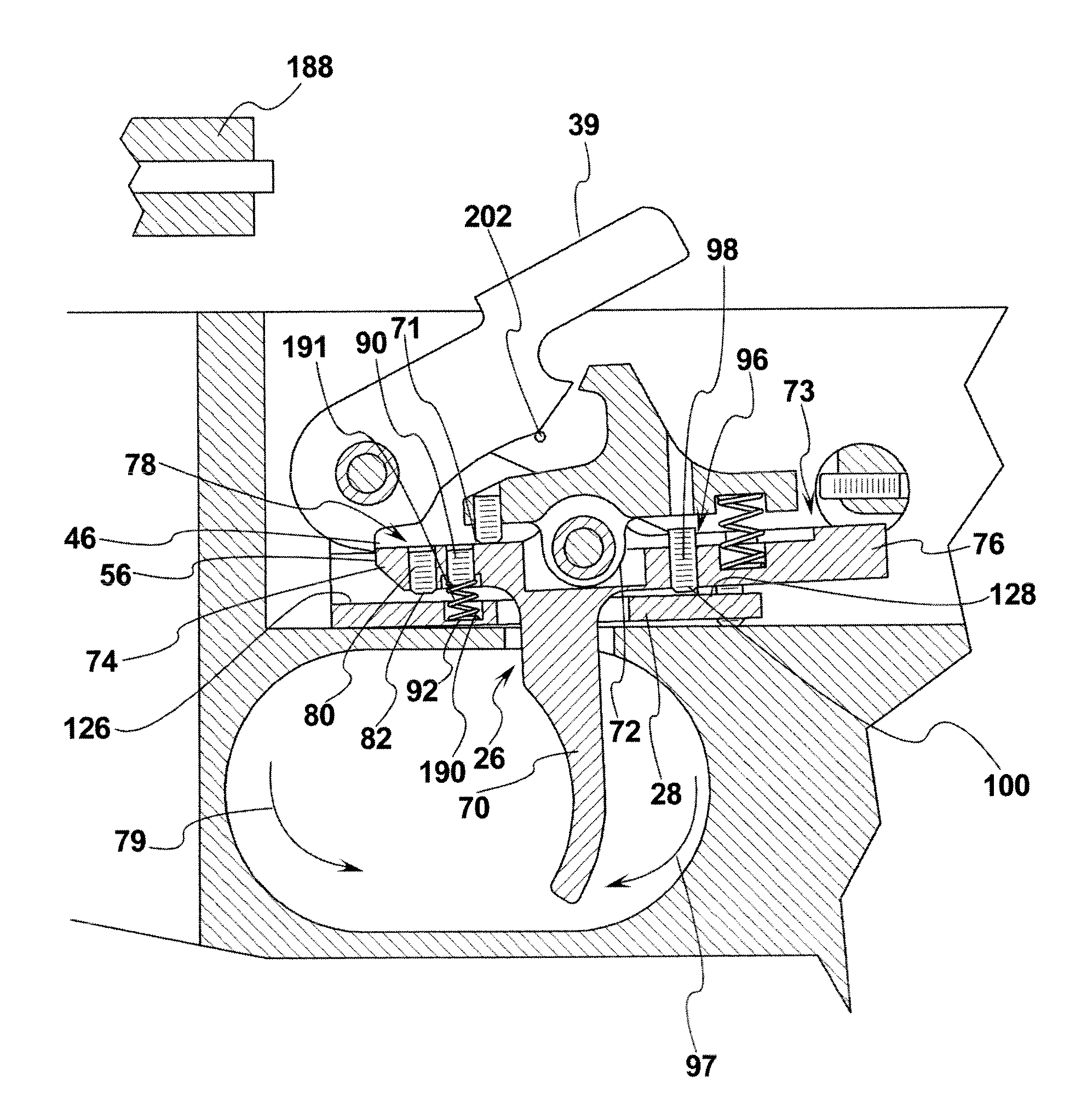
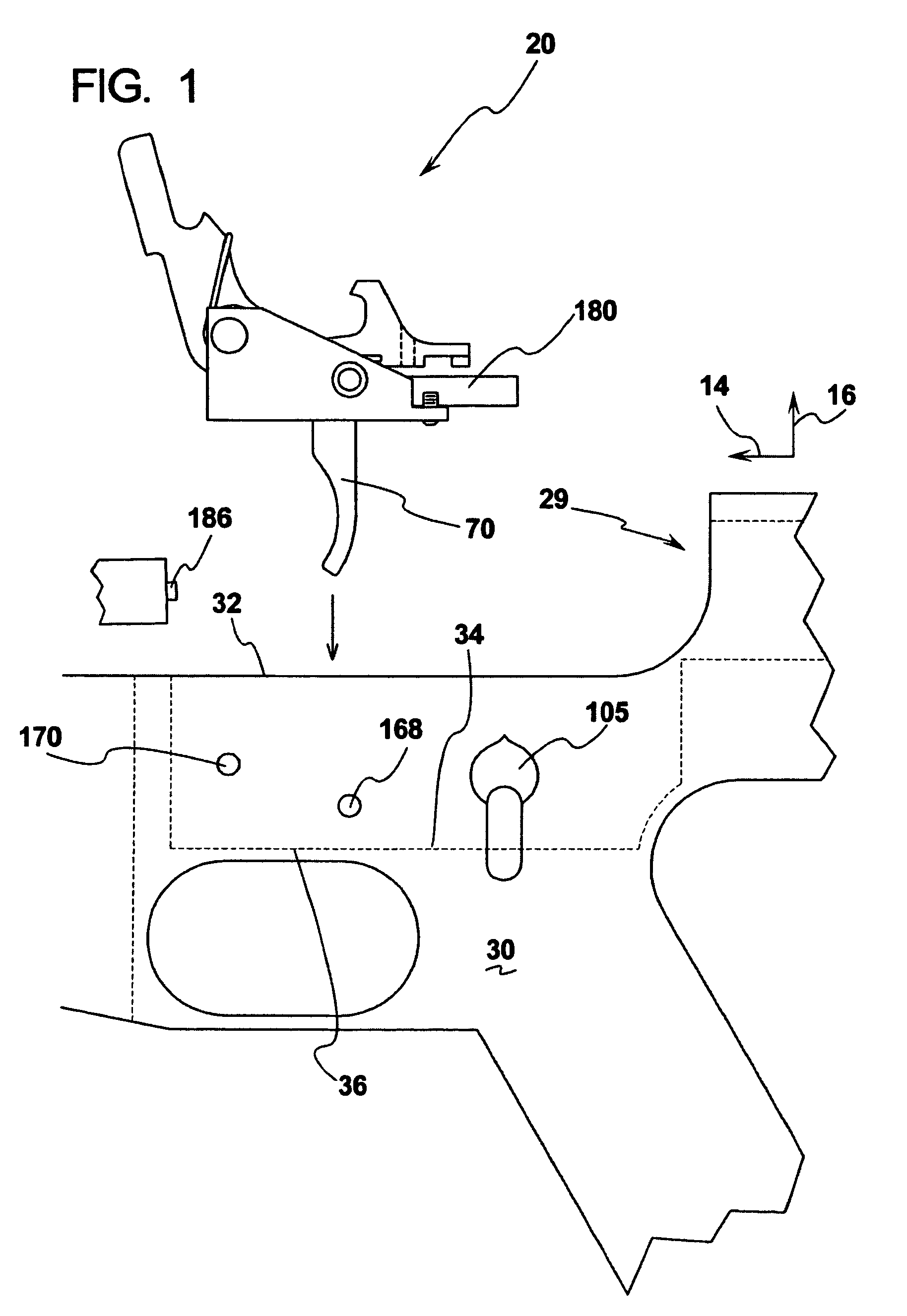
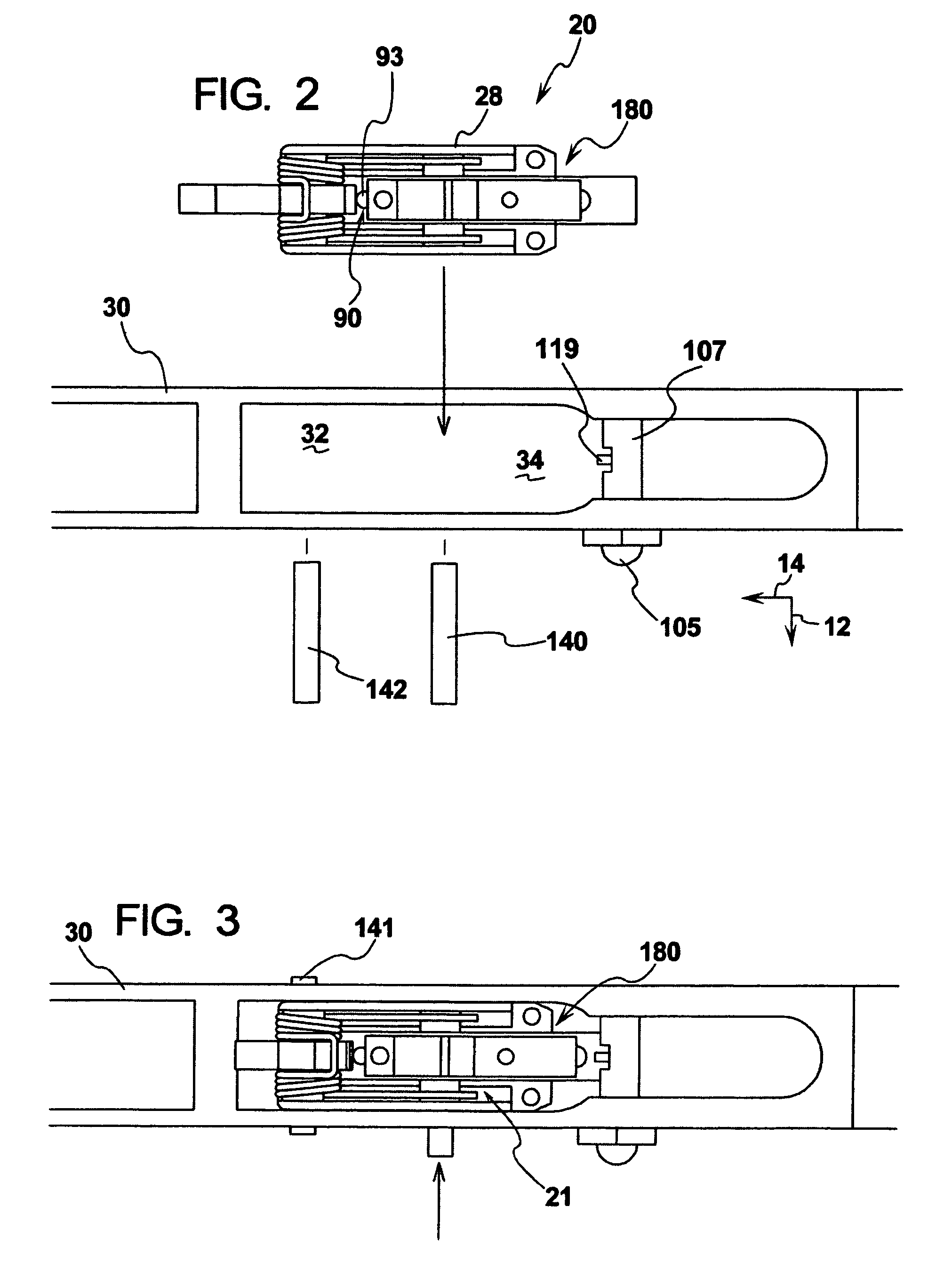
[0038]As shown in FIG. 1, there is a cross sectional side view of a trigger assembly 20 mounted within a lower receiver 30 of a 29 firearm. In one form, the firearm 29 is an AR-15 semiautomatic rifle. The lower receiver 30 comprises a central chamber area 32 having a lower support surface 34. The lower support surface 34 provides an opening 36 as adapted to allow the trigger extension 70 pass therethrough.

[0039]To aid the description of the invention, an axis system is defined that is shown in FIGS. 1 and 2 where the arrow 12 indicates a lateral direction, the arrow 14 indicates a longitudinal direction and the arrow 16 represents a transverse direction. Of course the trigger assembly 20 and the rifle can be positioned in various orientations and the axis system is provided for general purposes of describing the orientation of the components of the trigger assembly and not intended to limit the trigger assembly 20 to any specific orientation.

[0040]In general, as shown in FIG. 4 the ...


PUM


Abstract

A trigger assembly comprising a housing adapted to mount a trigger, hammer and sear therein. The housing has an adjustment feature adapted to fixedly mount the housing within the trigger chamber portion of the firearm. The trigger assembly is particularly conducive for an AR-15 type rifle and the various sear engagement surfaces are adapted to be adjustable irrespective of the various dimensions and tolerances of the underlying firearm. A safety system is employed that adjustably allows proper engagement of the trigger tail to properly engage and disengage the safety mechanism.

Description

RELATED APPLICATIONS[0001]This application claims priority benefit of U.S. Ser. No. 60 / 550,383, filed Mar. 5, 2004.BACKGROUND OF THE DISCLOSURE[0002]The apparatus relates to aftermarket (as well as OEM) trigger assemblies that are particularly adapted to be mounted in firearms. Specifically, in one form the apparatus is adapted to be retrofitted or initially installed to an AR-15 semiautomatic rifle.[0003]After market triggers have been provided for rifles to replace factory trigger assemblies. Factory trigger assemblies are notoriously poor where a shooter's accuracy is compromised where the trigger has excessive over travel (where the trigger will travel excessive rearwardly after releasing a hammer) or have what is referred to as take up. Take up is an undesirable movement of the trigger prior to releasing the hammer.[0004]In general, most shooters find it desirable when a trigger breaks like a “glass rod”. In some military applications the trigger pull is up to 12 lbs. It is des...

Claims


Application Information

Patent Timeline
IPC IPC(8): F41A19/16
CPCF41A17/46F41A17/74F41A17/82F41A19/45F41A19/12F41A19/14F41A19/16F41A19/10
Inventor GANGL, JOHN
Owner J & K IP ASSETS
Why Eureka
Try Eureka