Non-threaded structural insert for component attachment

a structural insert and component technology, applied in the field of fasteners, can solve problems such as degrading and achieve the effects of reducing localized stresses, avoiding discontinuities, and reducing the physical properties of composite materials

Inactive Publication Date: 2008-09-09
LOCKHEED MARTIN CORP
View PDF4 Cites 29 Cited by
  • Summary
  • Abstract
  • Description
  • Claims
  • Application Information

AI Technical Summary

Benefits of technology

[0008]The present invention provides a non-threaded structural insert that substantially addresses the above identified needs as well as others. More specifically, the present invention provides a non-threaded insert operable to transfer or couple a mechanical load to a structure, such as a composite structure. This non-threaded insert includes an upper insert having a noncircular cross section and a lower insert. The upper and lower insert mechanically couple via internal threads or other like means. The coupled insert may also receive within the structure a mechanical load which is then distributed to the structure. The noncircular upper insert is received within a noncircular receptacle wherein rotation of the upper insert within the receptacle is inhibited by mating the noncircular cross section of the upper insert to the noncircular receptacle. This fastener allows mechanical loads to be distributed to materials, such as composite materials, wherein traditional threaded fasteners would intensify mechanical stresses within the composite material.
[0009]A second embodiment provides a non-threaded insert operable to receive a mechanical load and couple the load to the structure. This non-threaded insert includes an upper and lower insert. The coupled non-threaded insert has a noncircular cross section that the structure receives within a noncircular receptacle to inhibit rotation of the non-threaded insert with respect to the structure. The contours of the upper surface of the upper insert and the lower surface of the lower insert conform to the contour of the upper surface or lower surface of the structure. This prevents discontinuities which would inhibit fluid flow over the structure such as an aircraft wing. Furthermore, aircraft pylons may couple to the structure, and receive mechanical loads and otherwise allow mechanical loads to be received by and distributed to the structure, without intensifying the localized stress often associated with threaded fasteners.
[0010]Yet another embodiment of a present invention provides a method of coupling the mechanical load to a structure such as an aircraft wing. This method involves mating an upper insert having a noncircular cross section to a noncircular receptacle located within the structure. Rotation of the upper insert within the noncircular receptacle is prevented by the mating of the upper insert to the noncircular receptacle. A lower insert mechanically couples to the upper insert. The coupled upper insert and lower insert are operable to couple to a mechanical load and mechanically couple and distribute that load to the structure while reducing localized stresses. The contour of the upper insert may match the contour of the upper surface of the structure in order to avoid discontinuities which would be experienced by fluid flow over the structure. The mechanical load may be mechanically coupled to the coupled upper and lower insert using a traditional mechanical fastener, such as a threaded fastener or other fastening system known to those skilled in the art.
[0011]The profile of the coupled upper and lower insert allow mechanical loads to be received and distributed across a structure without the structure experiencing the intense localized mechanical stresses often associated with threaded fasteners. This is particularly valuable when the structure is made from a material such as composite materials wherein localized regions of the composite material would experience significant stresses associated with the receiving of a threaded fastener. These stresses may significantly degrade the physical properties of the composite material.
[0012]The present invention provides significant advantages over the prior art, in that the present invention provides the ability to transfer loads from the attachment bolt to the structure without the need for internal threads within the structure as cracks in the structure often initiate from the thread roots. Additionally, the upper and / or lower inserts may be machined to be flush with the structure. Further, the upper and / or lower inserts may have a noncircular (i.e. non-symmetrical) cross section to prevent rotation of the non-threaded insert within the structure. Other features and advantages of the present invention will become apparent from the following detailed description of the invention made with reference to the accompanying drawings.

Problems solved by technology

These stresses may significantly degrade the physical properties of the composite material.

Method used


Image

  • Non-threaded structural insert for component attachment
  • Non-threaded structural insert for component attachment
  • Non-threaded structural insert for component attachment

Examples


Embodiment Construction

[0022]Preferred embodiments of the present invention are illustrated in the figures, like numerals being used to refer to like and corresponding parts of the various drawings.

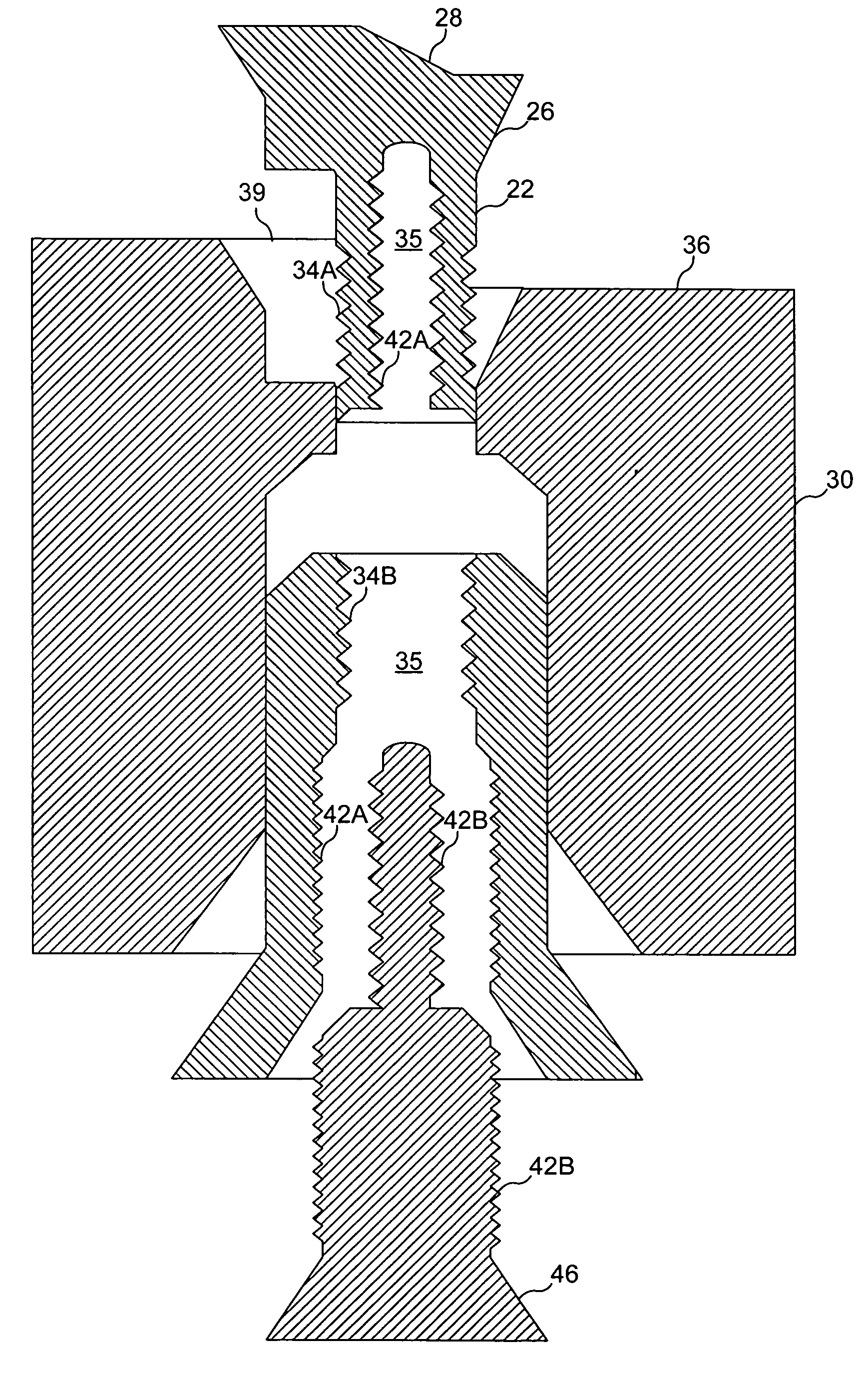
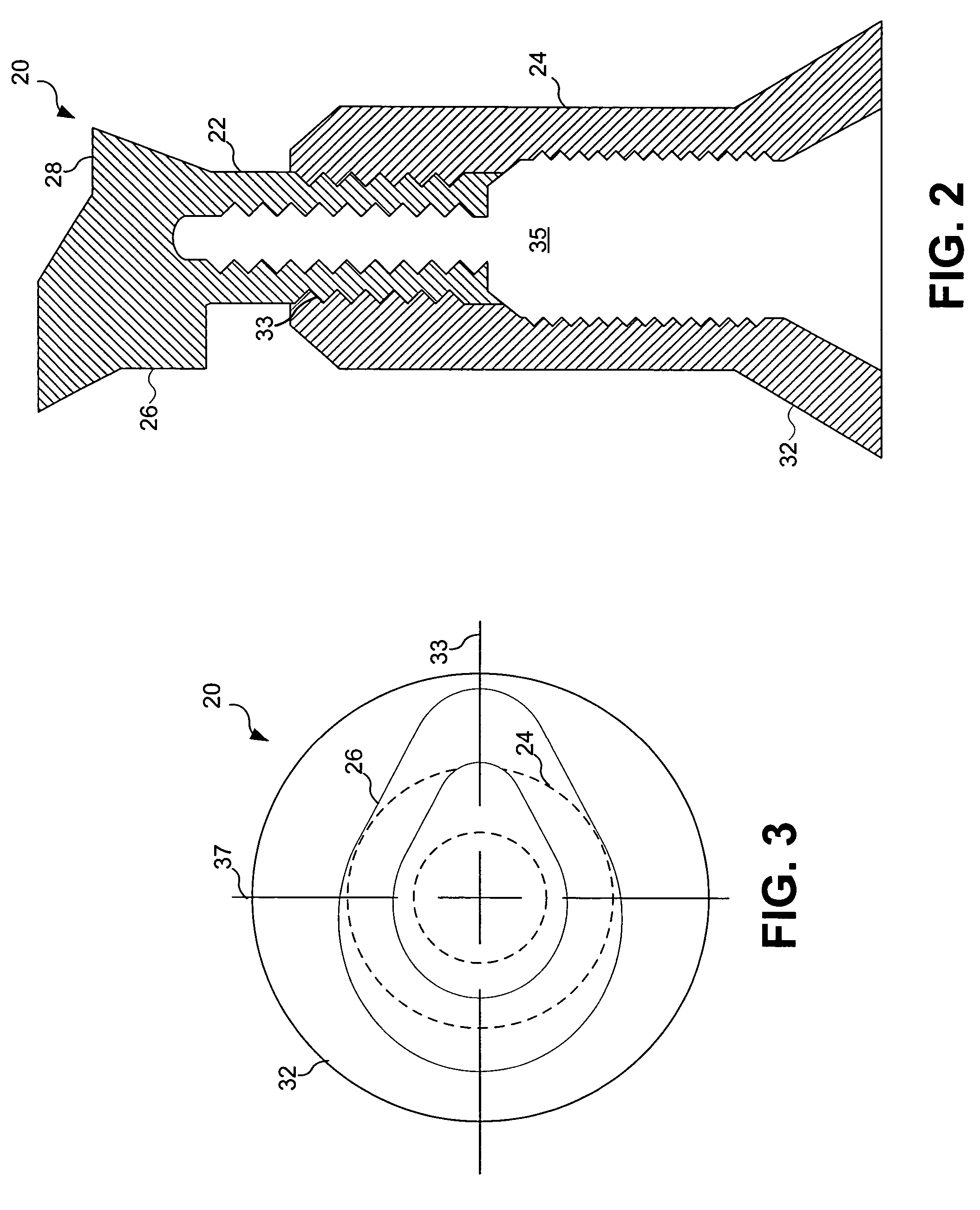
[0023]The present invention provides an integrated fastener assembly having the ability to transfer mechanical loads from an attachment bolt to a composite structure without the need for internal threads within the composite material structure. In one embodiment, the integrated fastener may have machined outer surfaces designed to be flush with the structure and a noncircular profile (i.e., non-symmetrical) that prevents rotation of the non-threaded fastener within the structure.

[0024]One particular embodiment calls for the attachment of structural loads in areas of high structural loading or stress. For example, a pylon within an aircraft may be located at a wing fold rib and experiences high loading and stresses during flight, takeoff, and landing. Traditional attachments have required internal threads in the...


PUM


Abstract

The present invention provides a non-threaded insert operable to transfer or couple a mechanical load to a structure. This non-threaded insert includes an upper insert having a noncircular cross section and a lower insert. The coupled upper and lower insert are received within the structure and are operable to receive a mechanical load which is then distributed to the structure. The noncircular cross section of the upper insert is received within a noncircular receptacle wherein rotation of the upper insert within the receptacle is inhibited by mating the noncircular cross section of the upper insert within the noncircular receptacle. This allows mechanical loads to be distributed to be better coupled to materials such as composite materials wherein traditional thread fasteners would intensify mechanical stresses within the coupled threads.

Description

GOVERNMENT INTEREST[0001]This invention was made with Government support under Contract Number N00019-02-C-3002 awarded by The Department of the Navy. The Government has certain rights in this invention.TECHNICAL FIELD OF THE INVENTION[0002]The present invention relates generally to fasteners and more particularly, a non-threaded structural insert operable to couple a mechanical load to a composite material structure.BACKGROUND OF THE INVENTION[0003]In recent years, the use of advanced composite structures has experienced tremendous growth in the aerospace, automotive, and many other commercial industries. While composite materials offer significant improvements in performance, they require strict control procedures in the manufacturing processes. The use of composite materials in military fighter aircraft has increased. For instance, in the F14, 0.8% of the total structural weight of the aircraft was made from composite. In the F15, F16 and F18, 1.6%, 2.5% and 9.5%, respectively, w...

Claims


Application Information

Patent Timeline
Patent Type & Authority Patents(United States)
IPC IPC(8): B64C1/12
CPCF16B19/02
Inventor DELAUNE, MICHAEL J.
Owner LOCKHEED MARTIN CORP
Why Eureka
Try Eureka