
Pseudorandom data pattern verifier with automatic synchronization

a data pattern and data verifier technology, applied in the field of communication links, can solve the problems of affecting the synchronization speed/phase control, introducing errors into the data, and affecting the synchronization speed, so as to achieve the effect of synchronizing more quickly, reducing the overhead of additional data, and reducing the bit error rate of a communication link

Inactive Publication Date: 2008-09-09
CF DB EZ +1
View PDF15 Cites 1 Cited by
  • Summary
  • Abstract
  • Description
  • Claims
  • Application Information

AI Technical Summary

Benefits of technology

[0011]The various embodiments of the systems and methods described above may provide a number of advantages over other systems. For example, the receiving end of a communications link can be synchronized more quickly than systems which look for predetermined patterns in received bit sequences, or which look up received bit patterns in a corresponding table. The bit error rate of a communications link can also be determined in real-time by transmitting portions of a pseudorandom bit sequence in idle codes contained in normal data transmissions. These bit sequences can be compared with locally generated sequences to identify bit errors that occur during transmission. Users may therefore be able to continually monitor the integrity of the communications link and repair or replace it if necessary. The present systems and methods may also be beneficial in that they can be implemented with only minimal additions to the existing hardware logic, and no additional data overhead.

Problems solved by technology

The transmission of the data over these communications links, however, may introduce errors into the data.
These errors may arise from a number of sources.
For example, because the transmission medium of the link may have several closely spaced data lines carrying high frequency signals, the signals may be subject to noise generated by electromagnetic interference.
This noise may degrade the signal enough to cause errors in the data.
It is typically inefficient, however, to wait for the predetermined sequence to appear.
This, however, would also be inefficient.

Method used


Image

  • Pseudorandom data pattern verifier with automatic synchronization
  • Pseudorandom data pattern verifier with automatic synchronization
  • Pseudorandom data pattern verifier with automatic synchronization

Examples


Embodiment Construction

[0020]A preferred embodiment of the invention is described below. It should be noted that this and any other embodiments described below are exemplary and are intended to be illustrative of the invention rather than limiting.

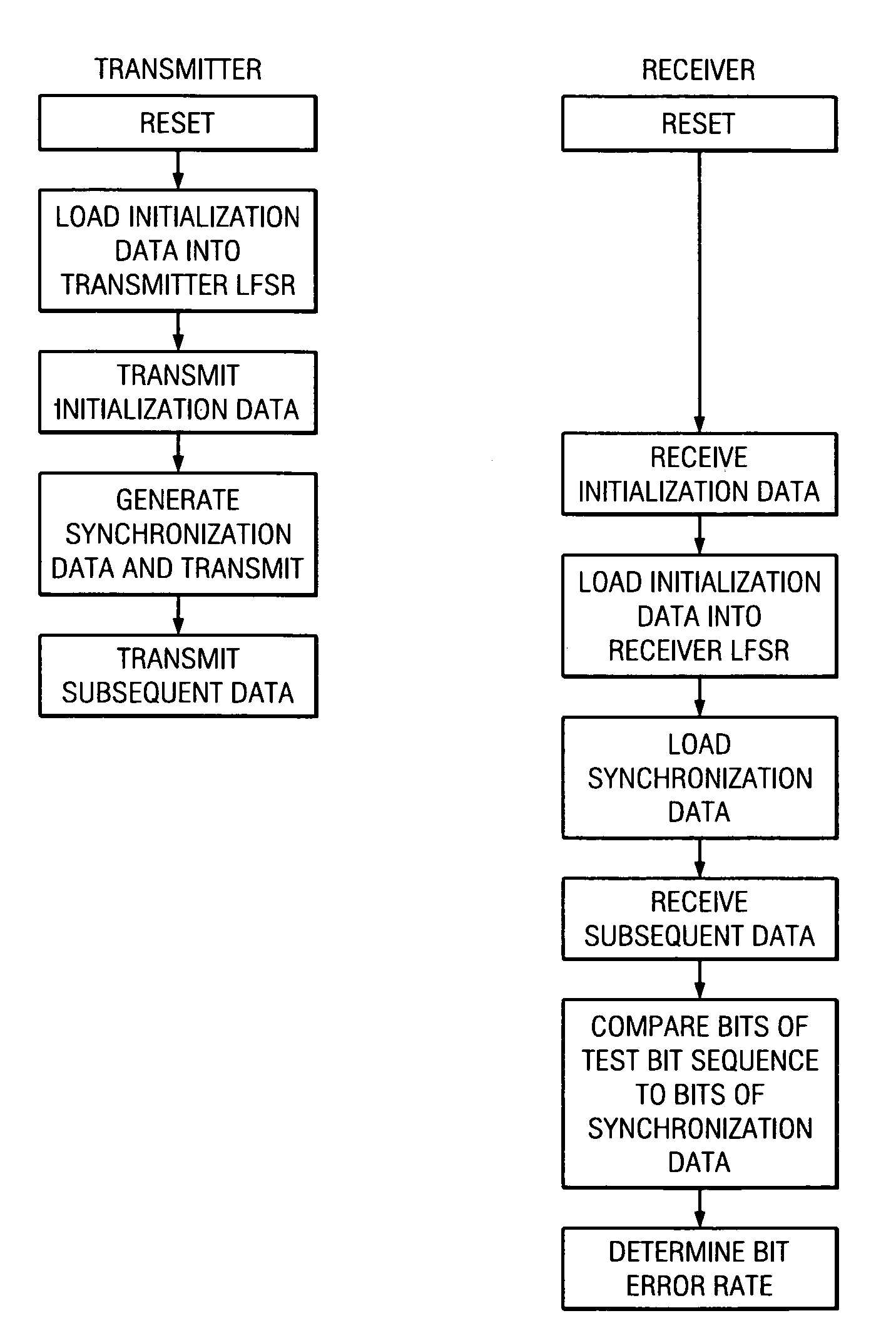
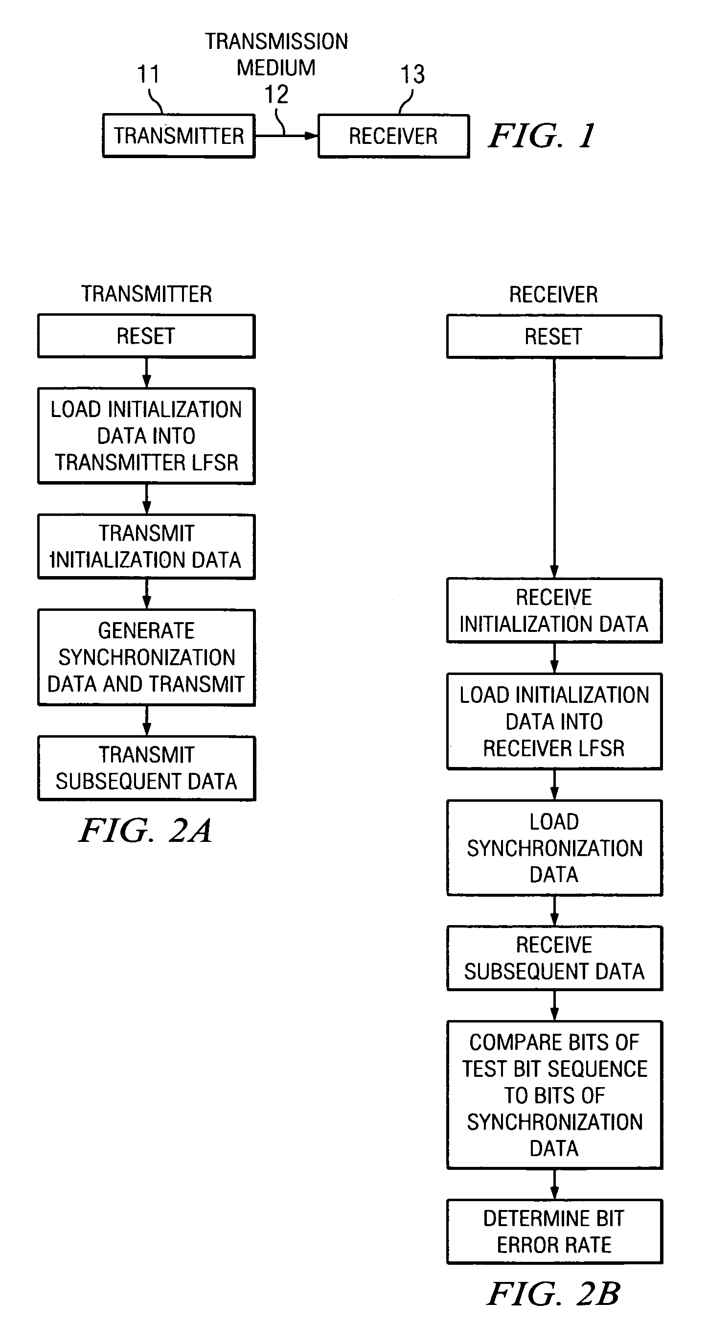
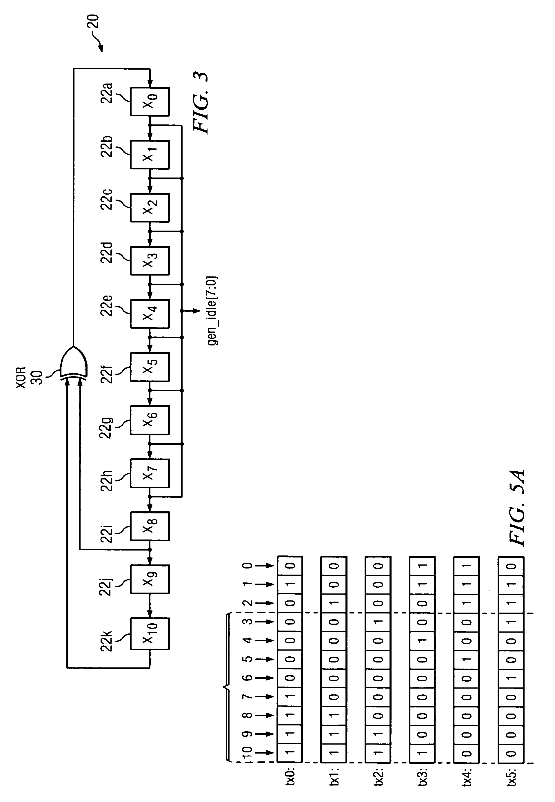
[0021]Broadly speaking, the invention comprises systems and methods for synchronizing a communications link. The synchronization mechanism further enables the determination of error rates of data transmissions over the communications link. In one embodiment, the transmitter and receiver of the communications link each contains a linear feedback shift register. Both linear feedback shift registers use the same polynomial to generate a pseudorandom bit sequence. The linear feedback shift register in the transmitter is initialized with a first bit sequence. At least a portion of this first bit sequence is transmitted over the communications link in an idle code and is used to initialize the shift register in the receiver. After a predetermined number of idle codes ...


PUM


Abstract

Systems and methods for synchronizing digital communications links, wherein one embodiment implemented in a receiver of a communications link comprises a shift register coupled to a transmission medium to receive synchronization data and a feedback circuit coupled to the shift register, wherein one or more cells of the shift register are configured to alternatively accept as input either a bit from a preceding cell or a received bit of synchronization data. The first occurs prior to synchronization, while the second occurs after synchronization. A counter is used to assert a signal indicating that the transmitter and receiver are synchronized.

Description

FIELD OF THE INVENTION[0001]The invention relates generally to communications links and more particularly to systems and methods for synchronizing these links and performing real-time testing of transmissions over the links to determine corresponding bit error rates.BACKGROUND OF THE INVENTION[0002]Digital communications links are often used to transmit data at very high rates from one point to another. The transmission of the data over these communications links, however, may introduce errors into the data. These errors may arise from a number of sources.[0003]For example, because the transmission medium of the link may have several closely spaced data lines carrying high frequency signals, the signals may be subject to noise generated by electromagnetic interference. This noise may degrade the signal enough to cause errors in the data.[0004]As a result of the potential for introducing errors into the data, various means are used to test the integrity of these communications links....

Claims


Application Information

Patent Timeline
Patent Type & Authority Patents(United States)
IPC IPC(8): H04L7/00H04L7/04
CPCH04L7/043H04L2007/045
Inventor VILA, DIEGO F.MATEUS, MARCUS S.
Owner CF DB EZ
Learn More