
Systems and methods for implementing contention-based optical channel access

a technology of optical channel access and contention, applied in the field of adhoc networks, can solve the problems of not economical or impractical use, constructing such an infrastructure is either impractical or not economical for the short-term use that is often required, and each wireless node is limited in the distance over which it can reliably transmi

Active Publication Date: 2008-09-09
RAYTHEON BBN TECH CORP
View PDF10 Cites 88 Cited by
  • Summary
  • Abstract
  • Description
  • Claims
  • Application Information

AI Technical Summary

Benefits of technology

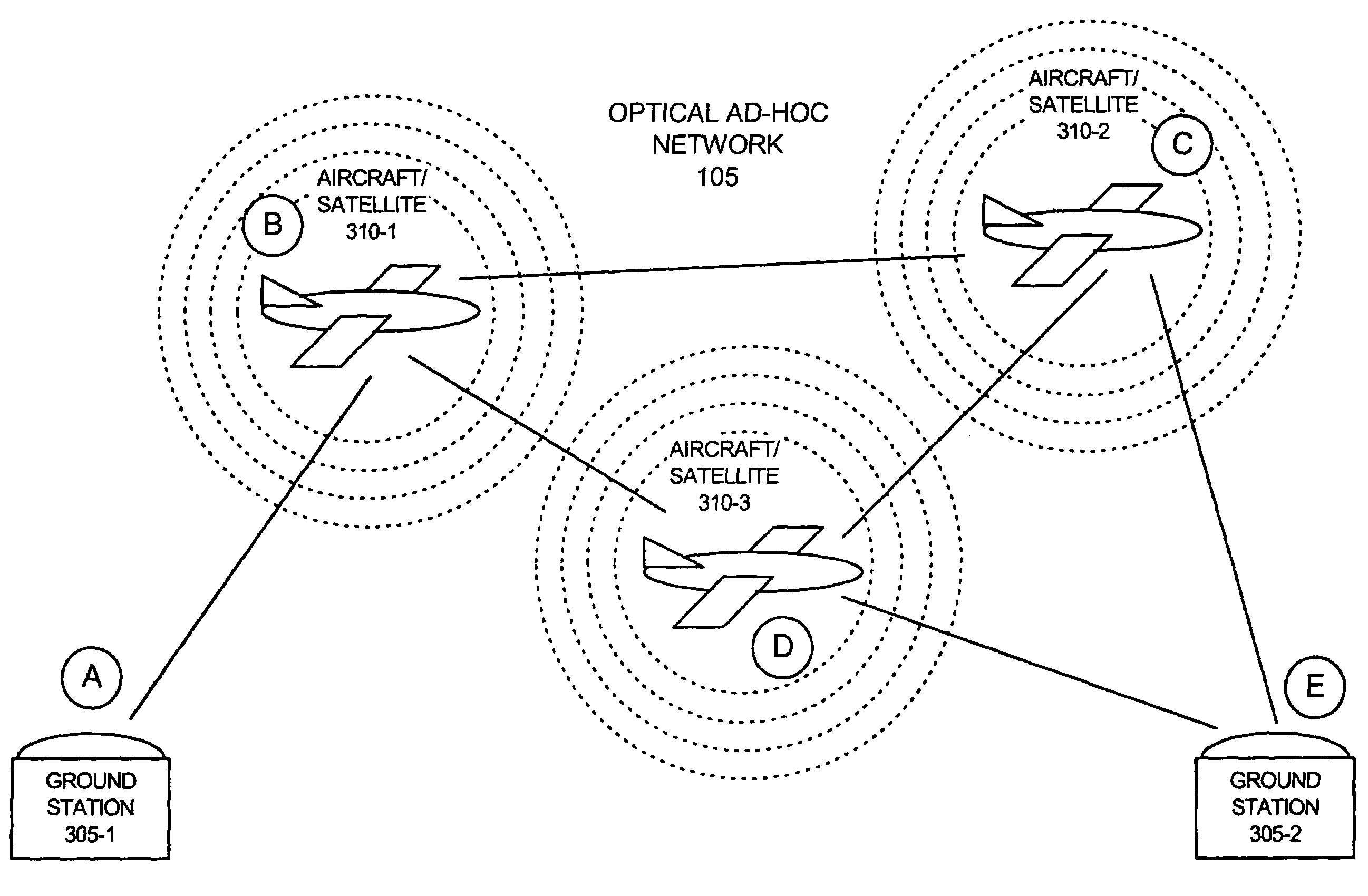
[0007]Systems and methods consistent with the present invention may use a hybrid RF / optical channel access scheme, where nodes use RF messaging to request access to the optical channels and, in response to the RF messaging, the ad-hoc nodes may establish optical links for high-speed communication via optical channels. In some exemplary embodiments, establishment of the optical links may include steering of one or more optical apertures, such as, for example, an optical telescope, to point towards the node to which an optical link is going to be established. Steering of the optical aperture may, thus, permit optical link establishment with mobile optical nodes that may frequently change position.

Problems solved by technology

Wireless data communication is often required in an environment where communications infrastructure, such as base stations or a wired backbone network, does not exist, or is not economical or is impractical to use.
For example, in military or emergency environments, adequate infrastructure often does not exist in necessary locations and constructing such an infrastructure would be either impractical or not economical for the short-term use that is often required.
Each wireless node, however, is limited in the distance over which it can reliably transmit, with transmission ranges of between a few feet and hundreds of feet being typical.
Therefore, in communication environments that span large areas or have significant radio interference, packets transmitted from a sending node must often be hopped over multiple nodes in the wireless network to reach a destination.
One drawback back with conventional multi-hop RF wireless networks is that the RF channel that is used to transmit data, such as packet data, can be relatively slow (e.g., kilobits or megabits per second of data throughput).

Method used


Image

  • Systems and methods for implementing contention-based optical channel access
  • Systems and methods for implementing contention-based optical channel access
  • Systems and methods for implementing contention-based optical channel access

Examples


Embodiment Construction

[0023]The following detailed description of the invention refers to the accompanying drawings. The same reference numbers in different drawings may identify the same or similar elements. Also, the following detailed description does not limit the invention. Instead, the scope of the invention is defined by the appended claims.

[0024]Systems and methods consistent with the present invention implement a hybrid RF / optical channel access scheme that may be employed in a multi-hop, ad-hoc network. The use of optical links for transmission of significant quantities of data, as opposed to conventional RF links, permits very high throughputs, on the order of multiple gigabits per second, in an ad-hoc environment where nodes may be moving around and links may be created and terminated with a high degree of frequency.

Exemplary Network

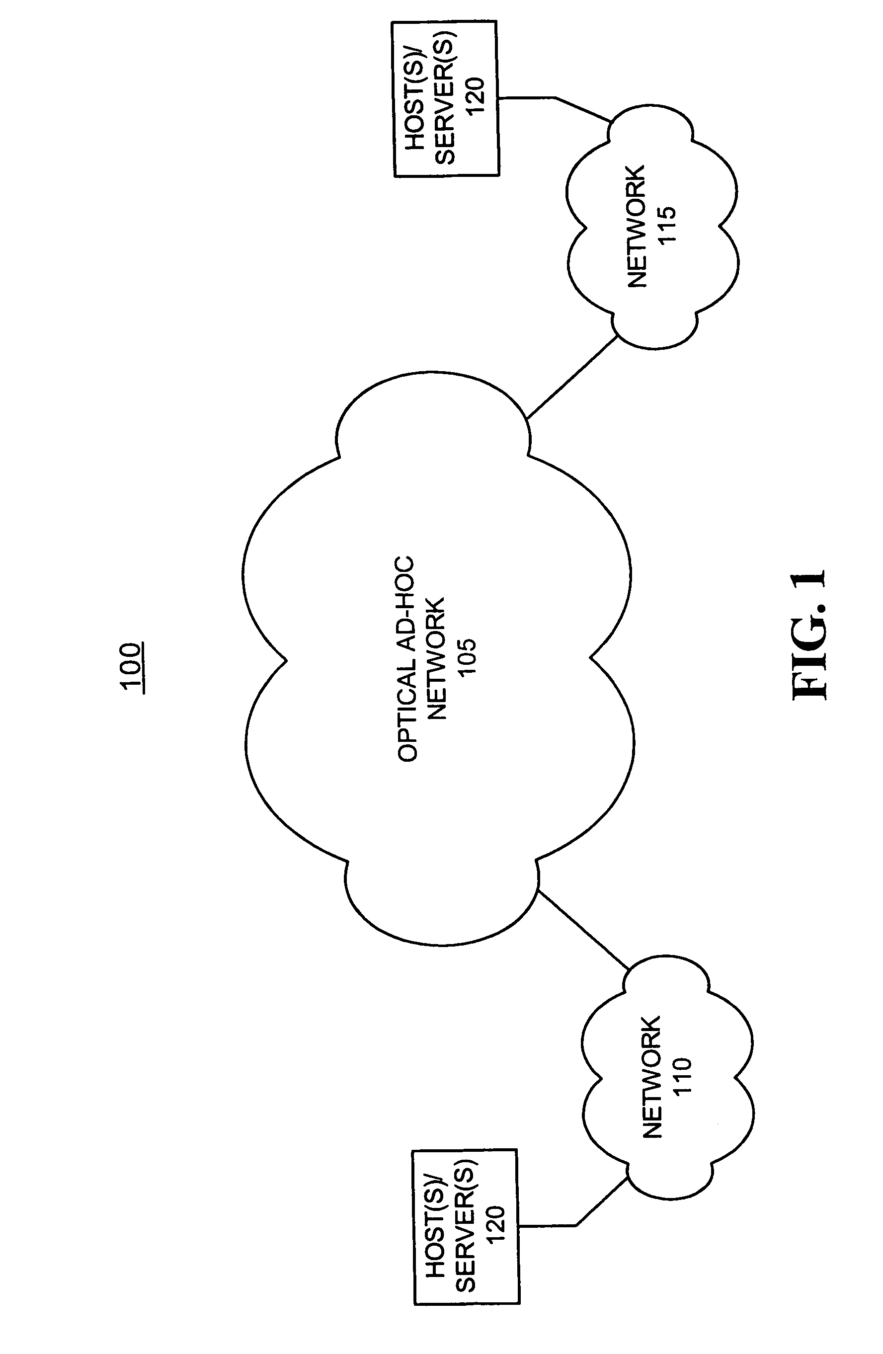
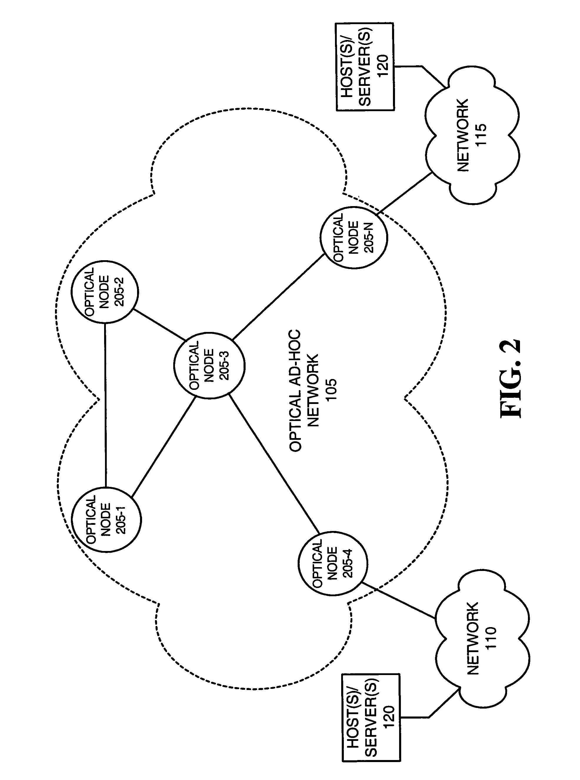
[0025]FIG. 1 illustrates an exemplary network 100 in which systems and methods may implement contention-based optical channel access consistent with the present i...


PUM


Abstract

A first node (205) in a network includes a non-optical transceiver (415) and an optical subsystem (410). The non-optical transceiver (415) sends a request message to establish an optical link from the first node (205) to a second node via electrical signals over an electrically transmissive medium. The optical subsystem (410) establishes an optical link between the first node and the second node based on the receipt of the request granted message and transmits data between the first node and the second node via optical signals over the optical link.

Description

RELATED APPLICATIONS[0001]The present application is related to commonly assigned U.S. patent application Ser. No. 10 / 716,270, entitled “Optical Ad-Hoc Networks,” and filed on Nov. 17, 2003; and commonly assigned U.S. patent application Ser. No. 10 / 715,738, entitled “Systems and Methods for Implementing Coordinated Optical Channel Access,” and filed on Nov. 17, 2003, the disclosures of which are hereby incorporated herein by reference in their respective entireties.FIELD OF THE INVENTION[0002]The present invention relates generally to ad-hoc networks and, more particularly, to systems and methods for implementing contention-based optical channel access in ad-hoc networks.BACKGROUND OF THE INVENTION[0003]Wireless data communication is often required in an environment where communications infrastructure, such as base stations or a wired backbone network, does not exist, or is not economical or is impractical to use. For example, in military or emergency environments, adequate infrastr...

Claims


Application Information

Patent Timeline
IPC IPC(8): H04B10/00
CPCH04B10/1149H04W4/02H04W84/18H04W8/005H04B7/18504H04W74/08
Inventor ELLIOTT, BRIG BARNUM
Owner RAYTHEON BBN TECH CORP
Learn More