Optical communication unit

a communication unit and optical technology, applied in the field of optical communication units, can solve the problems of large energy loss in the light emitting side and slow transmission speed in the contact communication, and achieve the effects of speeding up the communication speed, reducing optical power, and improving the efficiency of energy us

Inactive Publication Date: 2006-11-21
FUJITSU LTD
View PDF39 Cites 17 Cited by
  • Summary
  • Abstract
  • Description
  • Claims
  • Application Information

AI Technical Summary

Benefits of technology

[0011]It is an object of the present invention to provide an optical communication unit in which reduction of optical power and speed-up of a communication speed can be realized with the best balance therebetween by improving the efficiency of using energy for desired optical communication.

Problems solved by technology

The conventional type of optical communication unit, however, assumes spatial transmission as a communication mode, so that optical power is adjusted for a distance of spatial transmission by about 1 m. For this reason, when communication for a short distance (e.g. 0 m), namely so-called the contact communication is executed, the light in the light receiving side is much stronger than required, so that energy loss is large in the light emitting side.
Further, a transmission speed of 4 Mbps is appropriate, from a view point of efficiency of using light energy, for the spatial transmission for 1 m, but the transmission speed is too slow in the contact communication even if a balance with the optical power is taken into considerations.

Method used


Image

  • Optical communication unit
  • Optical communication unit
  • Optical communication unit

Examples


embodiment 1

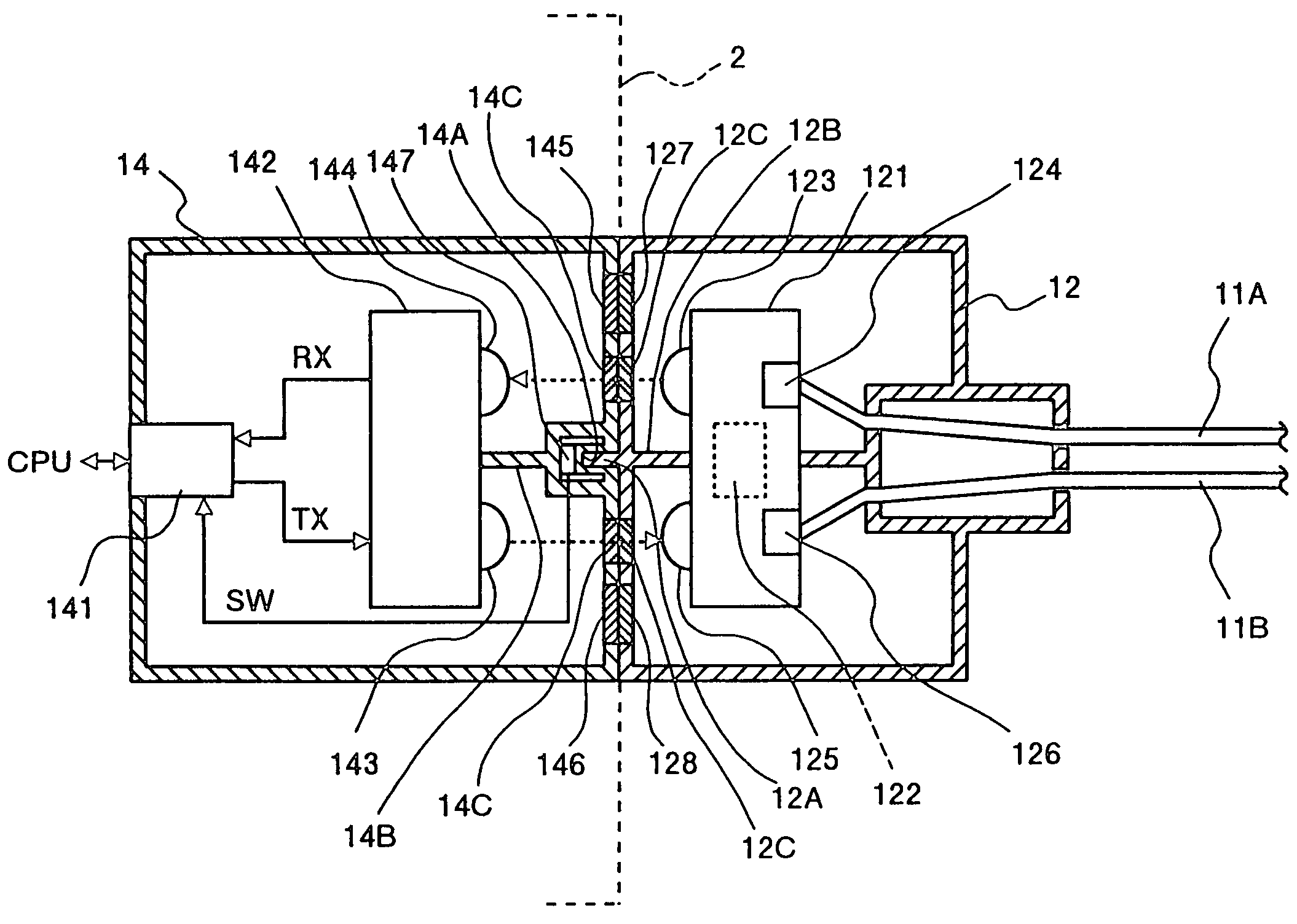
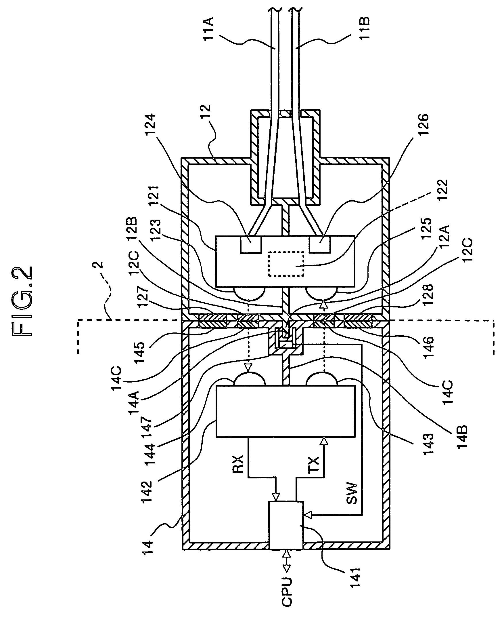
[0054]The pair of optical fiber cables 11A, 11B transmit optical signals (each obtained by converting an infrared ray to data) in two directions with one side of the cables for one direction. In Embodiment 1, one of the optical fiber cables 11A is a transmission path for transmitting an optical signal from the cable-side communication unit 13 to the cable-side communication unit 12, and the other side of the optical fiber cables 11B is a transmission path for transmitting an optical signal from the cable-side communication unit 12 to the cable-side communication unit 13.

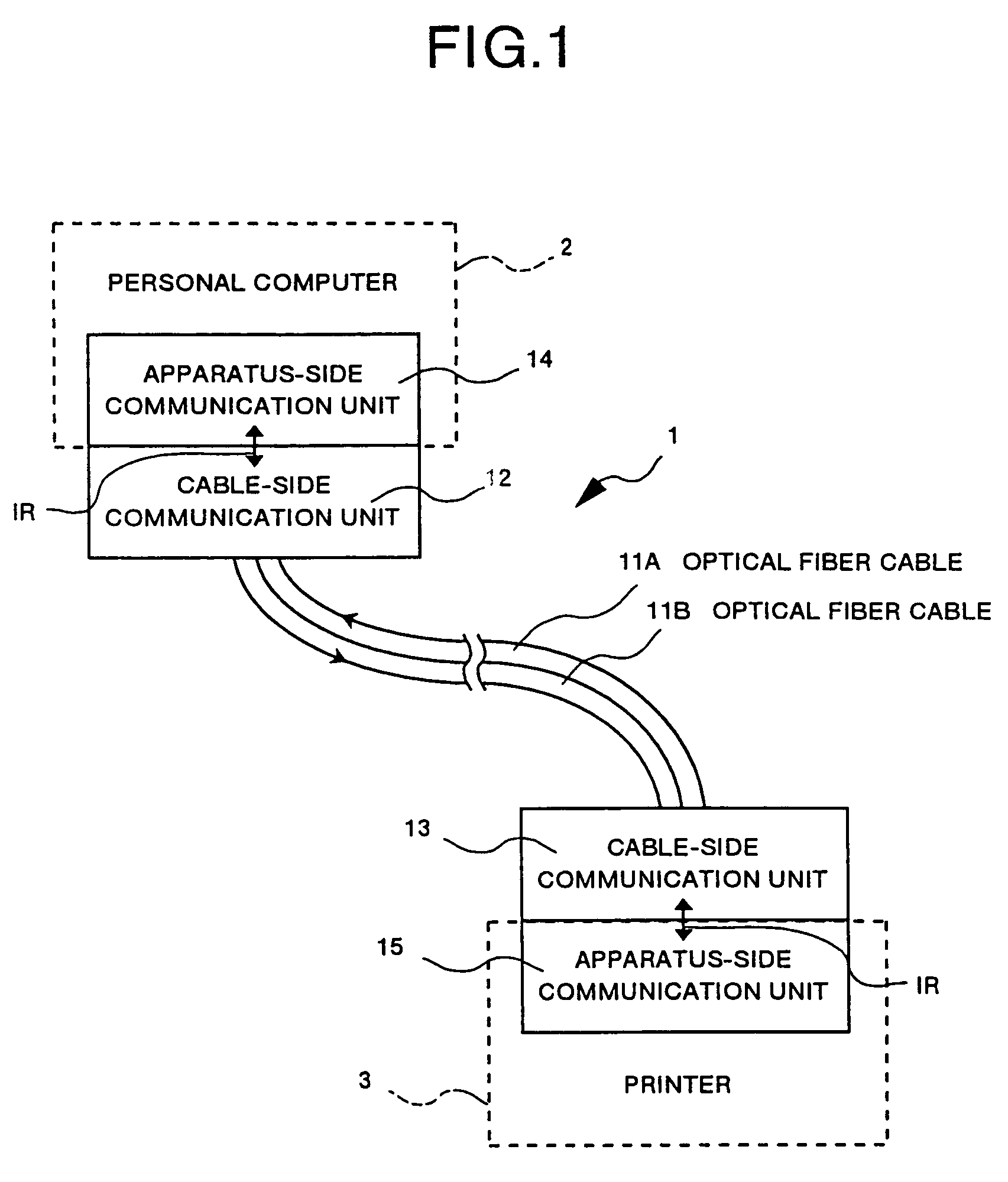
[0055]The optical communication unit 1 shown in FIG. 10 has system configuration in which the apparatus-side communication units 14, 15 are incorporated in a printer 3 as well as in a personal computer 2 respectively, to which the cable-side communication units 12, 13 each with, a cable (optical fiber cables 11A, 11B) are directly connected respectively. In this system configuration, infrared communication is possibl...

embodiment 2

[0104]In Embodiment 2, there is not provided in the cable-side communication unit 22 a shielding plate for optically shielding a light (infrared ray) emitted from the LED lens 223 against alight (infrared ray) received by the PD lens 225. As described above, the unit has no shielding plate provided therein, which enables realization of optical communications in two directions each for one-directional communication, namely half-duplex communication.

[0105]Provided on the same position (contact surface) as that where the projecting section 12A is provided in Embodiment 1 is a projecting section 22A having the same function in the cable-side communication unit 22. This projecting section 22A is a portion for engaging a concave section 24A provided on the contact surface of the apparatus-side communication unit 24 as a partner.

[0106]The apparatus-side communication unit 24 has a frame thereof formed in a box form. An LSI 241 electrically connected to the CPU of the personal computer 2 an...

embodiment 3

[0131]As described above, with Embodiment 3, a pair of cable-side communication units are connected to each other through an optical fiber cable, and infrared communications between units each in which the cable-side communication unit and the apparatus-side communication unit are directly connected to each other are controlled to a double speed based on the half-duplex system by using the optical module obtained by integrating the light receiving / emitting elements, so that contact communication based on the half-duplex system through a specified short distance between the communication units can be realized regardless of the length of the optical fiber cable, which enables high-speed optical communication and spatial efficiency on the whole is improved according to minimization of the optical module.

[0132]For this reason, optical power for executing infrared communication is sufficient only with energy suitable for the contact communication, so that it is possible to realize reduct...


PUM


Abstract

An optical communication unit has a pair of cable-side communication units provided for a full duplex communication system connected to each other with a pair of optical fiber cables, has apparatus-side communication units provided for full duplex communication system directly connected to the cable-side communication units respectively each to form a closest contact state therebetween, and provides controls for a speed to double speed in full duplex system by using an infrared ray IR between the closely contacted units.

Description

[0001]This application is a divisional of application Ser. No. 09 / 046,558, filed Mar. 24, 1998, now pending.FIELD OF THE INVENTION[0002]The present invention relates to an optical communication unit, and more particularly to an optical communication unit for executing data communication by using an infrared ray between equipment such as personal computers or a personal computer and a printer.BACKGROUND OF THE INVENTION[0003]FIG. 16 is a block diagram showing an optical communication unit according to, for instance, Japanese Patent Laid-Open Publication No. HEI 8-161089. The optical communication unit shown in FIG. 16 comprises a first communication unit 71 connected to a personal computer and functioning as an optical interface, and a second communication unit 81 connected to a printer and functioning as an optical interface.[0004]These first communication unit 71 and second communication unit 81 are arbitrarily spaced therebetween according to each place where a personal computer a...

Claims


Application Information

Patent Timeline
Patent Type & Authority Patents(United States)
IPC IPC(8): H04B10/00G06F3/00G02B6/42G06F13/00H04B10/07H04B10/112H04B10/25H04B10/80
CPCG02B6/4246H04B10/1143
Inventor MITUHASHI, TOMIO
Owner FUJITSU LTD
Why Eureka
Try Eureka