Performance enhanced TCP communication system

a communication system and high-speed technology, applied in the field of high-speed communication systems, can solve the problems of inefficient utilization of bandwidth, large time interval between the transmission of data by the sender host and its receipt of the acknowledgement, etc., and achieve the effect of reducing the effect of delay and extending the delay

Inactive Publication Date: 2007-11-13
HITACHI LTD +1
View PDF15 Cites 19 Cited by
  • Summary
  • Abstract
  • Description
  • Claims
  • Application Information

AI Technical Summary

Benefits of technology

[0004]It is an object of the present invention to provide a system which, when communication according to TCP or a similar protocol is carried out with use of a high-speed link with a large delay, can reduce the effect of the delay and allow high-speed communication without modifying the existing protocol.

Problems solved by technology

Where TCP communication is carried out through a link with a large delay, the time interval between the transmission of data by the sender host and its receipt of the acknowledgement may be considerable.
This may lead to the TCP window of the sender host becoming full as further data cannot be transmitted until the acknowledgement for the previously transmitted data packets from the receiver host has been received.
Thus, in conventional TCP communication through a large-delay link, though the transmission rate of the delay link may be high, the bandwidth may be utilized inefficiently because of this inherent constraint in the TCP protocol.
However, this would require the simultaneous reconfiguration of several thousands or more communication apparatuses, rendering this solution impractical.

Method used


Image

  • Performance enhanced TCP communication system
  • Performance enhanced TCP communication system
  • Performance enhanced TCP communication system

Examples


second embodiment

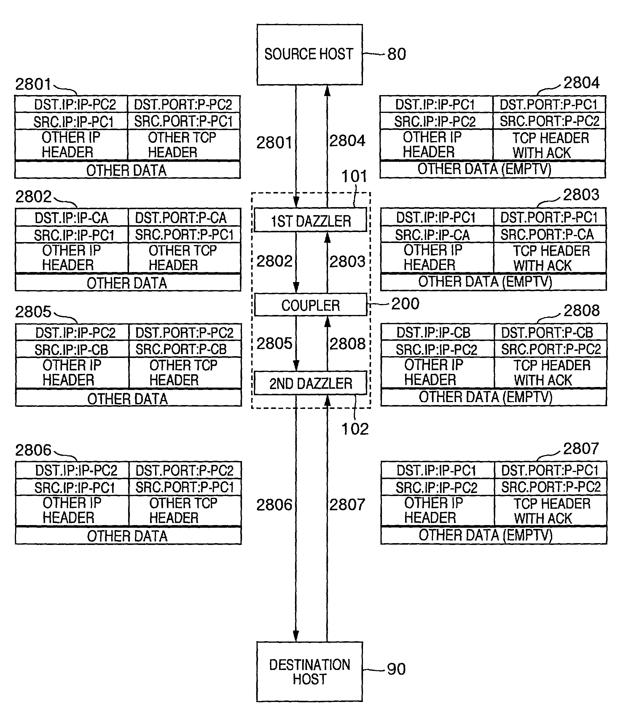
[0077]FIG. 12 shows the communication system of the invention and FIG. 13 shows the attributes of the TCP packets that are sent using the system.

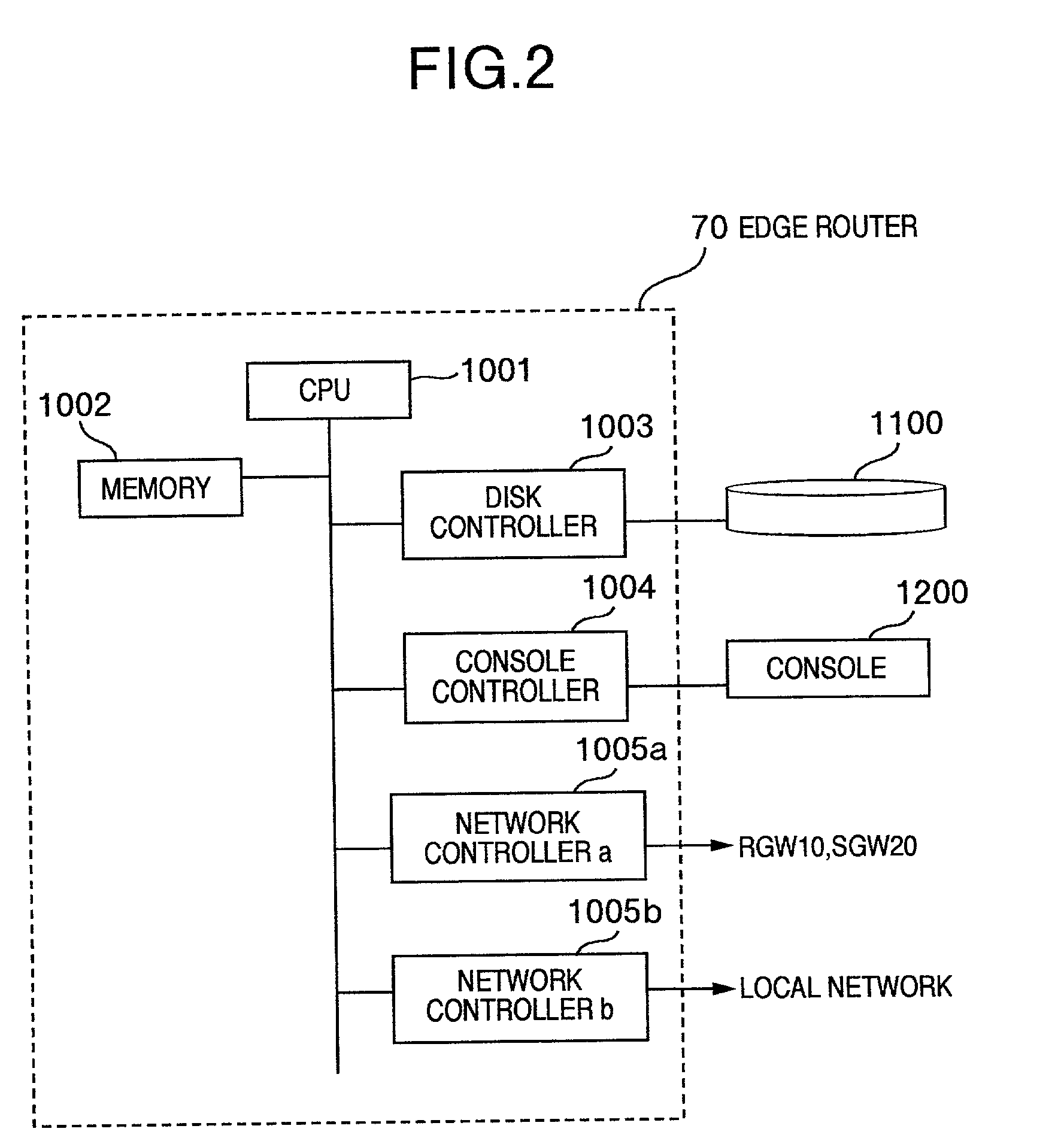
[0078]In this embodiment an edge router 70 is provided between a source host 80 and a destination host 90. The edge router 70 includes a first dazzler 101, a coupler 200, and a second dazzler 102.

[0079]Firstly, the source host 80 sends a TCP packet (the source address of which is the address of the source host 80, and the destination address is the address of the destination host 90) to the edge router 70 (step 2801). In FIG. 13, IP-PC1 and P-PC1 are the IP address and port number of the source host 80, and IP-PC2 and P-PC2 are the IP address and port number of the destination host 90.

[0080]The edge router 70 receives the TCP packet, which is accepted by the first dazzler 101. The first dazzler 101 conducts address translation according to translation rules which are registered in an address translation information table 1500 in advance. Mo...

first embodiment

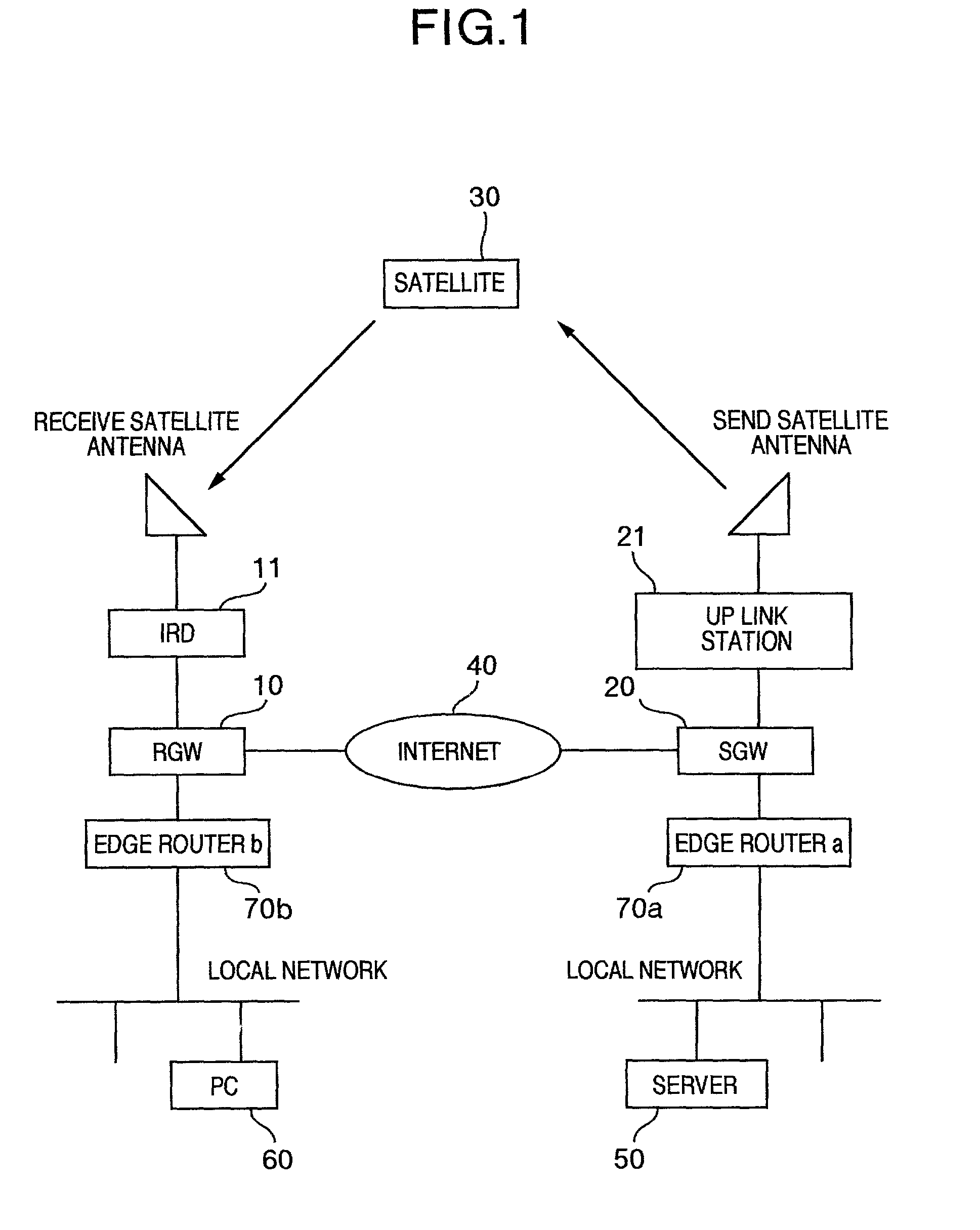
[0096]FIG. 15 shows communication architecture of the

[0097]As shown in FIG. 15, in the first edge router 70d, the dazzler conducts address translation of TCP packets from the source host 80 at the data link, in physical layer. The translated TCP packet is sent to the transport layer, and the TCP connection is terminated at this layer.

[0098]The coupler of the first edge router 70d is coupled to the coupler of the second edge router 70e via a connection according to any protocol. In this case, this connection is a TCP connection.

[0099]The coupler of the second edge router 70e is coupled to the destination host by a TCP connection. The dazzler of the second edge router conducts address translation of packets and forwards the TCP packets to the destination host 90.

[0100]In this case, 3 TCP connections “the source host 80—the 1st edge router 70d”, “the 1st edge router 70d—the 2nd edge router 70e”, and “the 2nd edge router 70e—the destination host 90” are established.

[0101]FIG. 16 shows t...


PUM


Abstract

A system for use with communications according to TCP, or a similar protocol, includes a sender host, one or more routers, and a destination host. Each router includes means for generating acknowledgement packets and translating addresses associated with data packets. When a data packet is received by a router, an acknowledgement packet is returned with a source address corresponding to the router and a destination address corresponding to the sender host. The sender host perceives the acknowledgement packet as having been sent by the destination host. As the acknowledgment packet is sent by the router, and not the destination packet is sent by the router, and not the destination host, this system allows acknowledgment packets to be received on a shorter timescale, reducing the effects of a link delay. Although the route between the sender host and the destination host is divided into multiple connections, the hosts perceive a single, conventional connection.

Description

BACKGROUND OF THE INVENTION[0001]The present invention relates to a system for high-speed communication using the Transmission Control Protocol (TCP), or a similar protocol, which requires a host to acknowledge the receipt of data.[0002]The TCP protocol, as documented in RFC (Request For Comments) 793, is widely used for high reliability data communication and has functions for error correction, flow control, etc. According to the TCP protocol, when a receiver host receives data, it sends an acknowledgement to a sender host. Where TCP communication is carried out through a link with a large delay, the time interval between the transmission of data by the sender host and its receipt of the acknowledgement may be considerable. This may lead to the TCP window of the sender host becoming full as further data cannot be transmitted until the acknowledgement for the previously transmitted data packets from the receiver host has been received. Thus, in conventional TCP communication through...

Claims


Application Information

Patent Timeline
Patent Type & Authority Patents(United States)
IPC IPC(8): H04J1/16H04J3/16H04L12/28H04L47/27
CPCH04L29/06H04L47/10H04L47/193H04L47/26H04L69/161H04L69/163H04L47/27H04L69/329H04L69/16H04L47/267H04L9/40
Inventor TAKATANI, YUKIHIRONONAKA, NAOMICHIKOIZUMI, MINORU
Owner HITACHI LTD
Why Eureka
Try Eureka