
Vehicle, vehicle control device and vehicle control method

a technology for vehicles and control devices, applied in the field of vehicles, can solve the problems of increased manufacturing costs and difficulty in dismounting vehicles, and achieve the effect of reducing costs

Inactive Publication Date: 2008-09-16
YAMAHA MOTOR CO LTD
View PDF9 Cites 78 Cited by
  • Summary
  • Abstract
  • Description
  • Claims
  • Application Information

AI Technical Summary

Benefits of technology

Prevents unforeseen vehicle operations, enhances safety by allowing users to control mode switching, and reduces manufacturing costs by eliminating the need for additional sensors and switches.

Problems solved by technology

This makes dismounting the vehicle difficult.
Providing the proximity sensor, however, results in increased manufacturing cost.

Method used


Image

  • Vehicle, vehicle control device and vehicle control method
  • Vehicle, vehicle control device and vehicle control method
  • Vehicle, vehicle control device and vehicle control method

Examples


Embodiment Construction

[0063]A vehicle according to preferred embodiments of the invention will be described below with reference to the drawings.

[0064](1) Configuration of the Motorized Balance Board

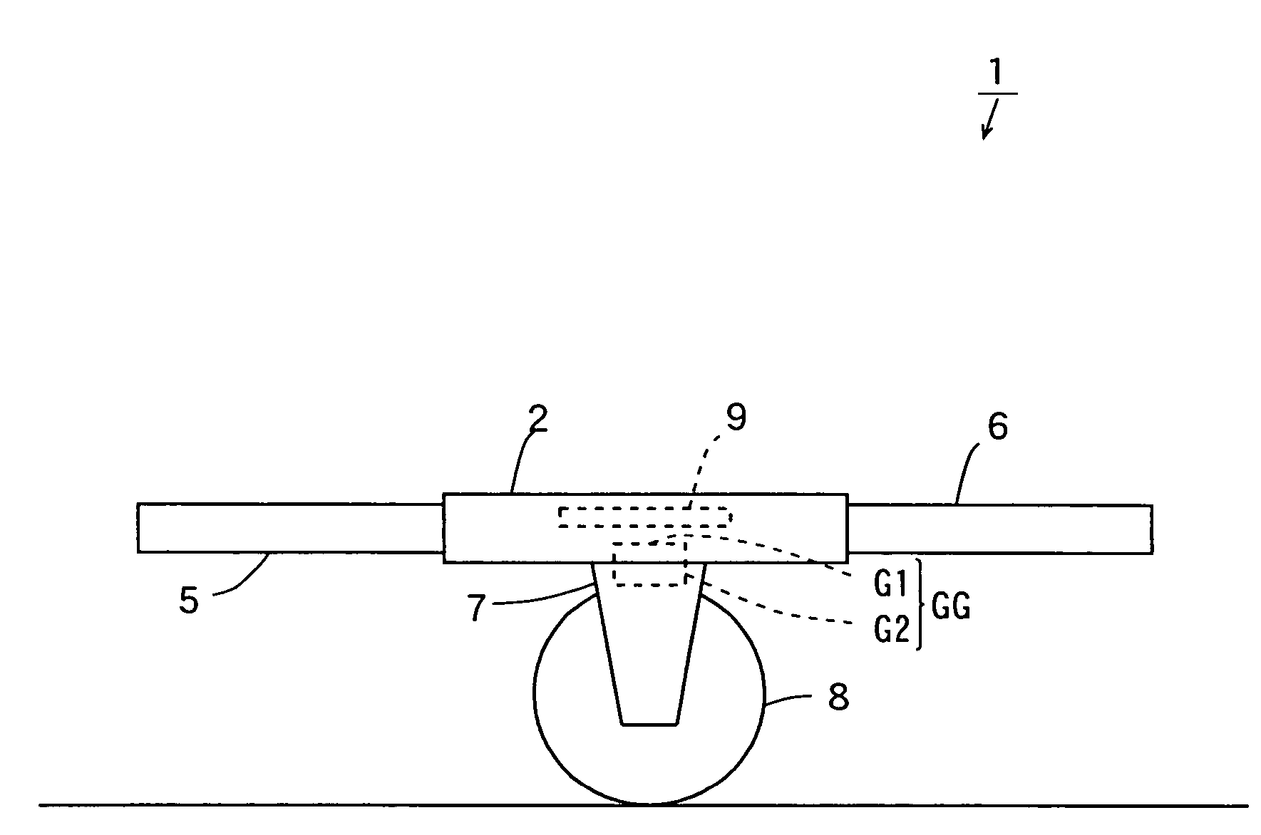
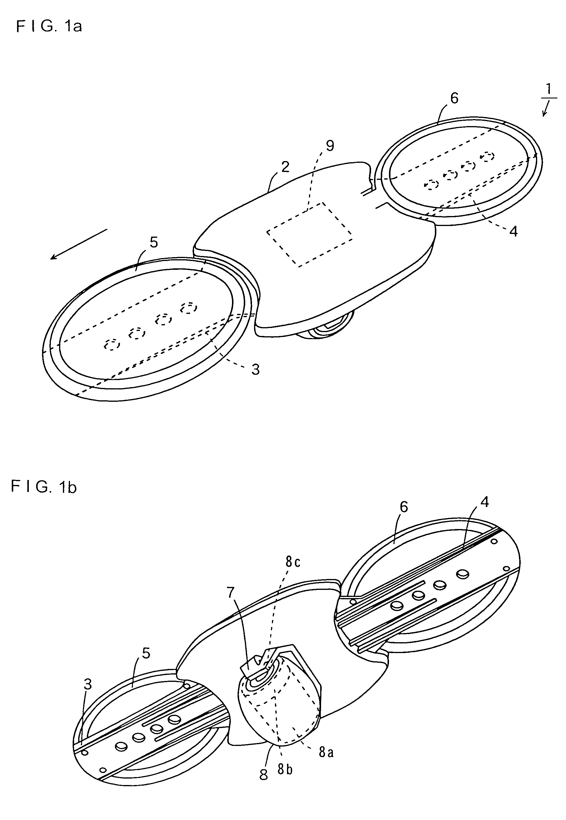
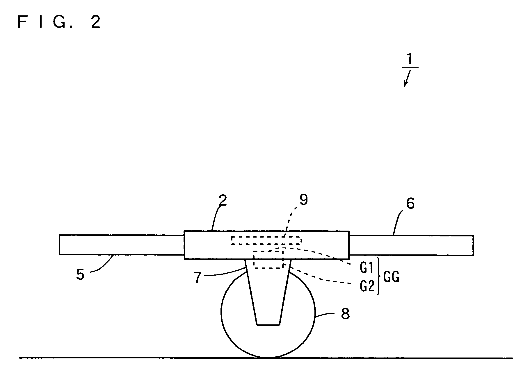
[0065]FIGS. 1 (a) and 1 (b) are schematic diagrams each showing the configuration of a vehicle according to a preferred embodiment of the present invention. A single-wheel motorized balance board 1 is shown in each of FIGS. 1 (a) and 1 (b) as an example of the vehicle according to a preferred embodiment of the present invention. FIG. 1 (a) is a diagram of the motorized balance board 1 viewed obliquely from above, and FIG. 1 (b) is a diagram of the motorized balance board 1 viewed obliquely from below. In the specification, the direction indicated by the arrow in FIG. 1 (a) defines the front, and the reverse direction defines the back.

[0066]As shown in FIGS. 1 (a) and 1 (b), the motorized balance board 1 has a plate-like main body 2 preferably made of fiber-reinforced plastics (FRP) or wood, for example. The f...


PUM


Abstract

A motorized balance board includes a gyrosensor. An arithmetic operation unit calculates a tilt angle change value based on a signal output from the gyrosensor. When the control mode is a standby mode, a control mode switch element switches the control mode to a riding mode when the absolute value of the tilt angle change value exceeds a riding angular velocity threshold. When the control mode is the riding mode, the control mode switch element switches the control mode to the standby mode when the absolute value of the tilt angle change value exceeds a descending angular velocity threshold.

Description

BACKGROUND OF THE INVENTION[0001]1. Field of the Invention[0002]The present invention relates to vehicles such as a unicycle and coaxial two-wheeled vehicle, a control device for such vehicles, and a control method for such vehicles.[0003]2. Description of the Background Art[0004]Conventionally, unstable vehicles such as unicycles, coaxial two-wheeled vehicles and the like which are capable of automatically keeping their balance are known (refer to JP 9-175462 A, JP 3070015 B or WO 00 / 75001, for example.) Such an unstable vehicle is configured so as to freely swing with the wheel as a supporting point.[0005]JP 9-175462 A discloses a unicycle that provides reduced swinging while being capable of adjusting the self-stabilizing force. This unicycle uses a control moment gyro (CMG) swinging reducing device to reduce the angular velocity of the axle about which the unicycle swings. This improves stability in the front or rearward direction and in the rightward or leftward direction durin...

Claims


Application Information

Patent Timeline
Patent Type & Authority Patents(United States)
IPC IPC(8): B60K28/14A63C17/01A63C17/08A63C17/12B60G1/00B60P1/00B62D1/00B62D37/00B62D49/08B62D61/00B62K1/00E02F3/76
CPCA63C17/004A63C17/01A63C17/016A63C17/08A63C17/12B62D37/00B62D61/00B60L11/18Y02T10/7258B60L2200/14B60L2260/34Y02T10/7005B60L50/51Y02T10/70Y02T10/72
Inventor HIRAMATSU, YUJI
Owner YAMAHA MOTOR CO LTD
Learn More