Centrifugal screen

a centrifuge and screen technology, applied in centrifuges, filtration separation, separation processes, etc., can solve the problems of affecting the quality of filtered products for food use, the welding of screen segments by welding precludes the replacement of individual screen segments, and the screen attachment is increased. , the effect of high viscosity and simple manner

Active Publication Date: 2008-09-16
JOHNSON SCREENS
View PDF13 Cites 27 Cited by
  • Summary
  • Abstract
  • Description
  • Claims
  • Application Information

AI Technical Summary

Benefits of technology

[0009]Thus, the invention relates to a centrifuge which has a separating screen arranged in a support basket and held in the bottom thereof by a lower flange. Said lower flange has a notched surface which penetrates into the screen. With this arrangement, welding operations are avoided, and the reliability of the attachment of the screen in the basket is increased in a simple manner.
[0010]According to a preferred embodiment of the centrifuge according to the invention, the screen and the basket both have an annular upper edge, and moreover, an upper flange is attached to the upper edge of the basket and covers the upper edge of the screen. A separating screen is typically held in the support basket by a single means of attachment at the lower end of the screen. The upper edge of the screen has proven to deteriorate rapidly due to the great stresses exerted by the tangential speed at the periphery of the screen and by the product to be filtered which has a high viscosity at this end. The upper flange makes it possible to keep the screen well pressed against the basket, to prevent deterioration of the screen at the upper edge, and serves as stop for the screen in order to prevent its ejection.
[0011]According to another preferred embodiment of the centrifuge according to the invention, the screen is a truncated cone and is formed by a number of segments attached in pairs by a joint with a T-shaped section. The joint with the T-shaped section can be removably attached to the basket by screws so as to avoid any welding operations for mounting the screen in the basket. Furthermore, each worn segment of the screen can be replaced independently of the other segments by rapid removal of the joint.
[0012]Preferably, the notched surface of the lower flange is comprised of notches that can receive a surface treatment, for example, case hardening, for the purpose of hardening them in order to reduce the effects of wear and tear over time.

Problems solved by technology

The welding of these segments requires much time and frequent checking of the weld points of the screen during use of the centrifuge.
Furthermore, the materials used for executing the welds can be detrimental to the quality of filtered products for food use.
Additionally, assembly of the screen segments by welding precludes replacement of an individual segment of the screen.
Furthermore, maintaining the separating screen in the basket requires the presence of a stop in the form of an annular bar welded on the interior periphery of the screen supporting the lower flange which presses the screen against the basket, which is expensive to implement.

Method used


Image

  • Centrifugal screen
  • Centrifugal screen
  • Centrifugal screen

Examples


Embodiment Construction

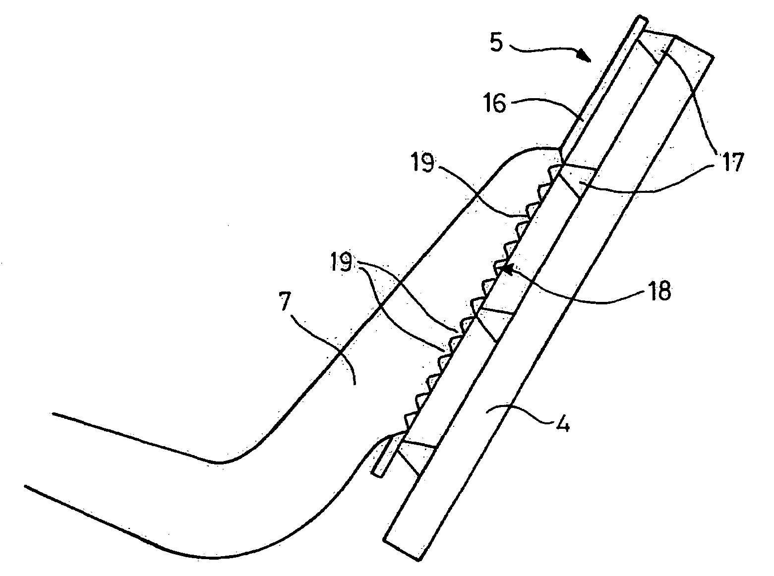
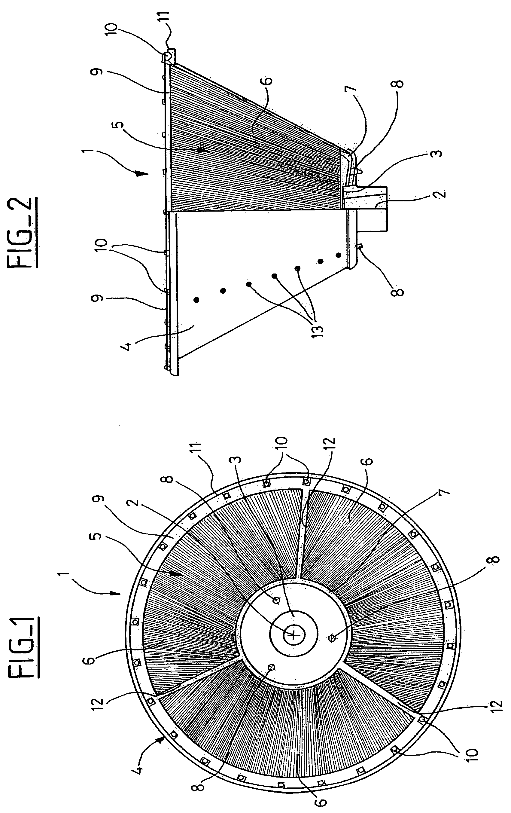
[0020]Represented in FIGS. 1 and 2 is drum 1 of a centrifuge according to the invention, which is a truncated cone with axis 2. Bottom 3 of the drum is made up of the smaller section of the truncated cone. Drum 1 is rotated about its axis 2 during operation of the centrifuge, where bottom 3 is shown oriented downwards in FIG. 2 but can be oriented differently depending on the centrifuge. Drum 1 is composed of a truncated-cone-like support basket 4 which can be seen in FIG. 2, and of truncated-cone-like separating screen 5, separating screen 5 being arranged inside support basket 4. Support basket 4 is a metallic mesh or a rigid perforated metal sheet with openings allowing the flow of the filtrates. Separating screen 5 in the embodiment presented in FIG. 1 is composed of three essentially trapezoidal screen segments 6 attached in a removable manner to support basket 4. More particularly, segments 6 are attached at their lower edge by means of lower securing flange 7 which is annular...


PUM

PropertyMeasurementUnit
timeaaaaaaaaaa
viscosityaaaaaaaaaa
lengthaaaaaaaaaa

Abstract

The centrifuge has truncated-cone-like separating screen arranged in support basket and held in the bottom thereof by lower flange. Lower flange has notched surface which penetrates into screen. The screen and the basket both have an annular upper edge and an upper flange which is attached to the upper edge of the basket and covers the upper edge of the screen. Finally, the screen is formed by a number of segments attached in pairs by a joint with a T-shaped section.

Description

CROSS-REFERENCE TO RELATED APPLICATIONS[0001]This application claims priority to French Patent Application Serial No. FR 04 51664, filed on Jul. 27, 2004, which application is herein incorporated by reference in its entirety.BACKGROUND OF THE INVENTION[0002]1. Field of the Invention[0003]The present invention concerns a centrifuge which has a truncated-cone-like separating screen arranged in a support basket and held in the bottom thereof by a lower flange.[0004]2. Description of the Related Art[0005]A centrifuge of the type indicated above is known through EP 1400284. It is used as an apparatus for filtering by centrifugation in order to separate a solid from a liquid and, more particularly, in order to separate sugar crystals from syrup in a conventional sugar refining process. The truncated-cone-like separating screen or strainer covers the truncated-cone-like interior wall of the support basket.[0006]The screen is made up of a number of essentially trapezoidal segments which are...

Claims


Application Information

Patent Timeline
Patent Type & Authority Patents(United States)
IPC IPC(8): B01D33/06B04B7/18C13B30/10
CPCB04B7/18
Inventor REIG, RAPHAEL
Owner JOHNSON SCREENS
Why Eureka
Try Eureka