Apparatus and method for compensating secondary currents used in differential protection to correct for a phase shift introduced between high voltage and low voltage transformer windings

a technology of differential protection and secondary current, applied in emergency protective circuit arrangements, instruments, measurement devices, etc., can solve the problems of incorrect ct polarities, failure to automatically compensate secondary current, and failure to open and isolate faulted power system elements from the remainder of the power system

Active Publication Date: 2008-09-16
SCHWEITZER ENGINEERING LABORATORIES
View PDF8 Cites 39 Cited by
  • Summary
  • Abstract
  • Description
  • Claims
  • Application Information

AI Technical Summary

Benefits of technology

[0018]In accordance with yet another aspect of the invention, a method is provided for providing an operational vector-group compensation setting pair to a power transformer differential relay where the operational vector-group compensation setting pair automatically provides correction for a phase shift occurring between currents of a first winding and a second winding of a power transformer of a three-phase power system. The method includes, based on a first and a second plurality of digitized current sample streams derived from a plurality of secondary currents corresponding to currents of the first winding and the second winding respectively, calculating a corresponding first and a corresponding second plurality of phasors. The method further includes selecting a pair of vector-group compensation settings based on three-phase operate current values calculated using the first and second plurality of phasors, and applying a first vector-group compensation setting of the selected vector-group compensation setting pair to the first plurality of phasors to form a first set of three test phasors and applying a second vector-group compensation setting of the selected vector-group compensation setting pair to the second plurality of phasors to form a second set of three test phasors. The method further includes after adjusting each of the three test phasors of the first set by one-hundred and eighty degrees to form an adjusted first set of three test phasors and if phase angles of each of the adjusted first set of three test phasors is within a pre-determined angle range of phase angles of each of the like-phase phasors of the second set of three test phasors, enabling application of the vector-group compensation setting pair as the operational vector-group compensation pair.

Problems solved by technology

If the operate current exceeds some threshold, or pickup current, the current differential relay issues a tripping signal to an associated power circuit breaker(s), causing it to open and isolate the faulted power system element from the remainder of the power system.
For example, commissioning using traditional electromechanical relays required labor intensive manual intervention by a commissioning engineer to check for errors such as improper current transformer installation which may result in incorrect CT polarities.
Unfortunately, none of the prior art systems and methods for commissioning provided a way to automatically compensate secondary currents used by current differential protection schemes to correct for a phase shift occurring between the currents of the HV winding and the LV winding of a power transformer.
When not corrected, such a phase shift between the currents of the HV winding and the LV winding may result in power transformer differential relay mis-operation.

Method used


Image

  • Apparatus and method for compensating secondary currents used in differential protection to correct for a phase shift introduced between high voltage and low voltage transformer windings
  • Apparatus and method for compensating secondary currents used in differential protection to correct for a phase shift introduced between high voltage and low voltage transformer windings
  • Apparatus and method for compensating secondary currents used in differential protection to correct for a phase shift introduced between high voltage and low voltage transformer windings

Examples


Embodiment Construction

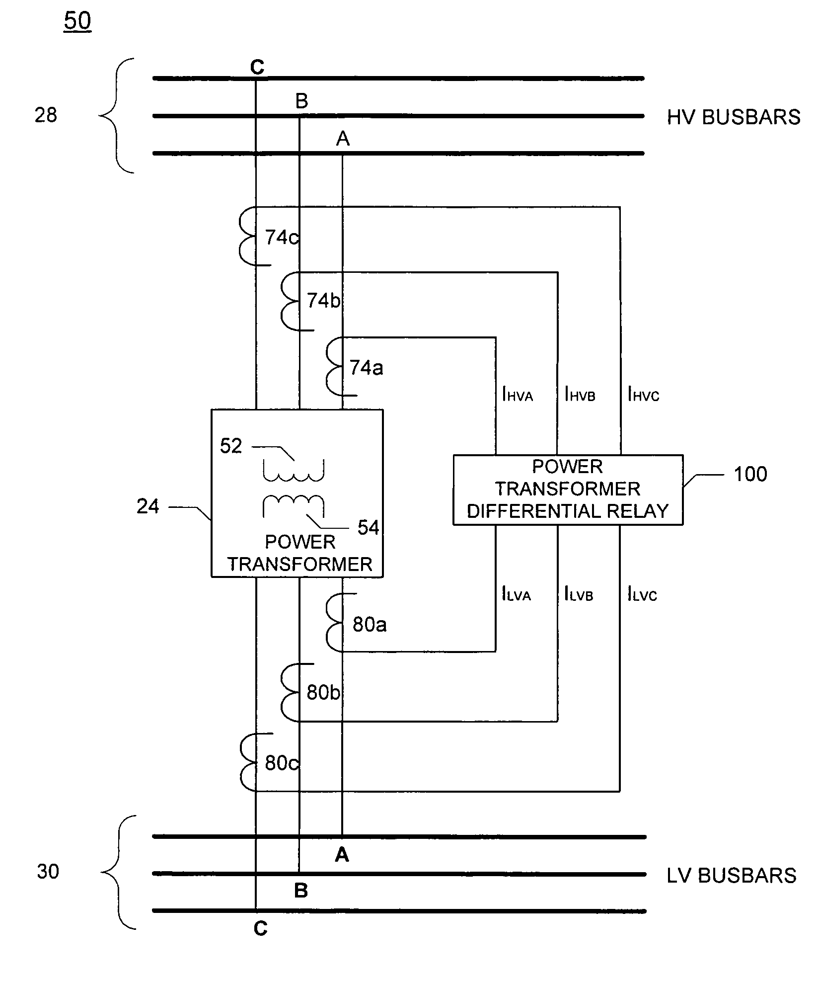
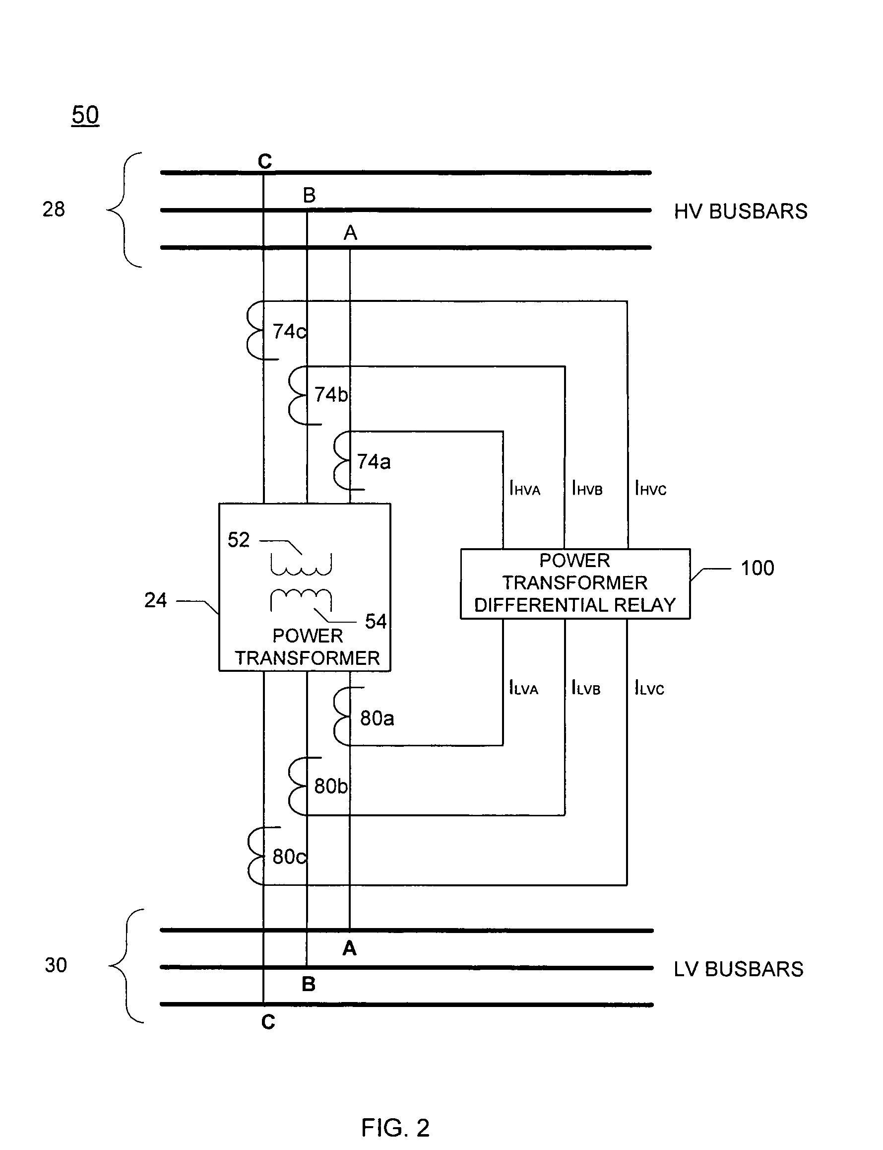
[0028]In addition to selecting and providing to a power transformer differential relay, an operational vector-group compensation setting pair that automatically compensates secondary currents to correct a phase shift between the primary currents of the HV and LV windings, implementation of the apparatus and methods disclosed herein also provides a commissioning report to a commissioning engineer. Among other things, the commissioning report includes commissioning information such as phase rotation (e.g., angular displacement between the windings), the measured load current during the commissioning process, and the recommended vector group setting resulting from these measurements. Subsequent application of the operational vector-group compensation setting pair also automatically removes zero-sequence current from the secondary currents used by the power transformer differential relay during power system operation.

[0029]For ease of discussion, aspects of the present invention can be ...


PUM


Abstract

Provided is an apparatus and method for providing to a differential relay an operational vector-group compensation setting pair that automatically provides correction for a phase shift occurring between currents of at least two windings of a power transformer. The method includes calculating a first and second plurality of phasors using secondary currents derived from respective first and second winding of the at least two windings. The method also includes selecting one pair of vector-group compensation settings based on operate current values calculated using different pair combinations of the vector-group compensation settings applied to the first and second plurality of phasors. The method further includes comparing phase angles of like-phase phasors to determine if the phase angles are within a pre-determined angle range, and enabling application of the selected pair of vector-group compensation settings as the operational vector-group compensation setting pair if the phase angles are within the pre-determined angle range.

Description

CROSS-REFERENCE TO RELATED APPLICATIONS[0001]This application claims benefit under 35 U.S.C. §119(e) of U.S. Provisional Application Ser. No. 60 / 671,370, entitled “An Apparatus and Method for Compensating Secondary Currents Used in Differential Protection to Correct for a Phase Shift Introduced Between High Voltage and Low Voltage Transformer Windings”, filed on Apr. 14, 2005, naming Casper Labuschagne as inventor, the complete disclosure thereof being incorporated by reference.BACKGROUND OF THE INVENTION[0002]The present invention generally relates to power system protection, and more specifically, to an apparatus and method for compensating secondary currents used in differential protection to correct for a phase shift introduced between high voltage and low voltage transformer windings.[0003]Electric utility systems or power systems are designed to generate, transmit and distribute electrical energy to loads. In order to accomplish this, power systems generally include a variety ...

Claims


Application Information

Patent Timeline
Patent Type & Authority Patents(United States)
IPC IPC(8): G01R19/00
CPCH02H7/045G01R35/02
Inventor LABUSCHAGNE, CASPERFISCHER, NORMANN
Owner SCHWEITZER ENGINEERING LABORATORIES
Why Eureka
Try Eureka