Disk drive with heater for slider and control method thereof

a slider and slider technology, applied in the field of disk drives, can solve the problems of head element section protruding, design not meeting the requirements of read performance, and head element section may also protruding, so as to reduce the possibility of collision

Inactive Publication Date: 2008-09-16
HITACHI GLOBAL STORAGE TECH NETHERLANDS BV
View PDF8 Cites 9 Cited by
  • Summary
  • Abstract
  • Description
  • Claims
  • Application Information

AI Technical Summary

Benefits of technology

[0011]With the above-mentioned situation behind, the present invention was made concerning the technique which uses a heater to protrude a head element section so as to adjust its clearance above the magnetic disk. It is a feature of the present invention to allow this technique to reduce the possibility of collision between the head element section and the magnetic disk.
[0012]According to a first aspect of the present invention, there is provided a disk drive which comprises: a slider which flies above a spinning recording disk; a head element section disposed on the slider; a heater which is disposed on the slider and adjusts the clearance between the head element section and the recording disk by protruding the head element section through thermal expansion; an actuator which carries the slider; a ramp onto which a part of the actuator runs in order to retract the slider to the outside of the recording disk; and a controller which in a process to load the retracted slider to the recording disk, keeps the heater in OFF state until a predetermined timing after the slider is moved to the recording disk and the part of the actuator is discharged from the ramp. During the load process, even if the flying attitude is not stable, it is possible to reduce the possibility of collision between the head element section and the recording disk since the heater is kept in OFF state until the predetermined timing after the slider is moved to the recording disk and the actuator is discharged from the ramp.
[0013]According to a second aspect of the present invention, the disk drive according to the above-mentioned first aspect further includes a temperature sensor wherein, until a predetermined timing after the slider is moved to the recording disk and the part of the actuator is discharged from the ramp, the controller keeps the heater in OFF state if the detected temperature by the temperature sensor is not lower than a reference temperature, and keeps the heater in ON state if the detected temperature by the temperature sensor is lower than the reference temperature. Temperature-based heater control can reduce the possibility of collision between the head element section and the recording disk while making it possible to read out necessary data.

Problems solved by technology

TFC heats up the heater by supplying current to it, which causes the head element section to protrude due to thermal expansion.
Even in normal operation, the head element section may also protrude due to thermal expansion.
For example, it is therefore likely that the design does not realize satisfactory read performance in low temperature environment while satisfactory read performance is attained in high temperature environment.
On the other hand, TFC may increase the possibility of collision between the magnetic disk and the head element section since the head element section is more protruded than without TFC.
In this process, the head slider is more likely to collide with the magnetic disk since its flying attitude is unstable.
However, TFC further increases the possibility of collision between the head element section and the magnetic disk during load / unload since the head element section is protruded as mentioned above.

Method used


Image

  • Disk drive with heater for slider and control method thereof
  • Disk drive with heater for slider and control method thereof
  • Disk drive with heater for slider and control method thereof

Examples


Embodiment Construction

[0042]An embodiment of the present invention will be described below. For clarity, omission and simplification are made where appropriate in the following description and the drawings. In addition, where the same component appears again in another drawing, the same reference numeral is given and its description is omitted for the purpose of clarity.

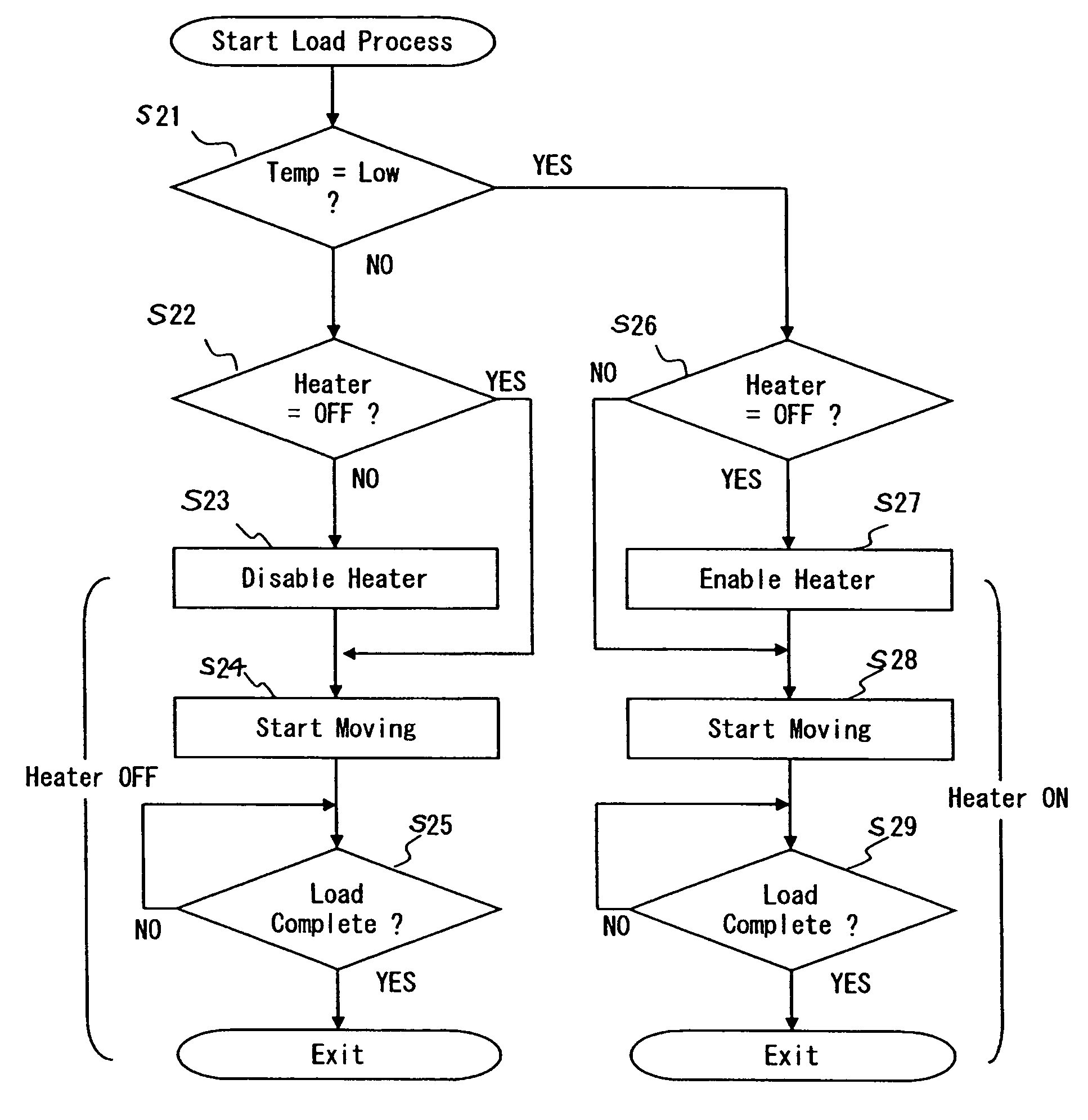
[0043]A disk drive in the present embodiment employs a load / unload system with a ramp to retract a head slider thereto from the magnetic disk. In addition, the head slider is provided with a TFC (Thermal Flyheight Control) heater to adjust the clearance between the head and the medium by means of thermal expansion. One of the characteristics of the present embodiment concerns the control of the TFC heater during load / unload.

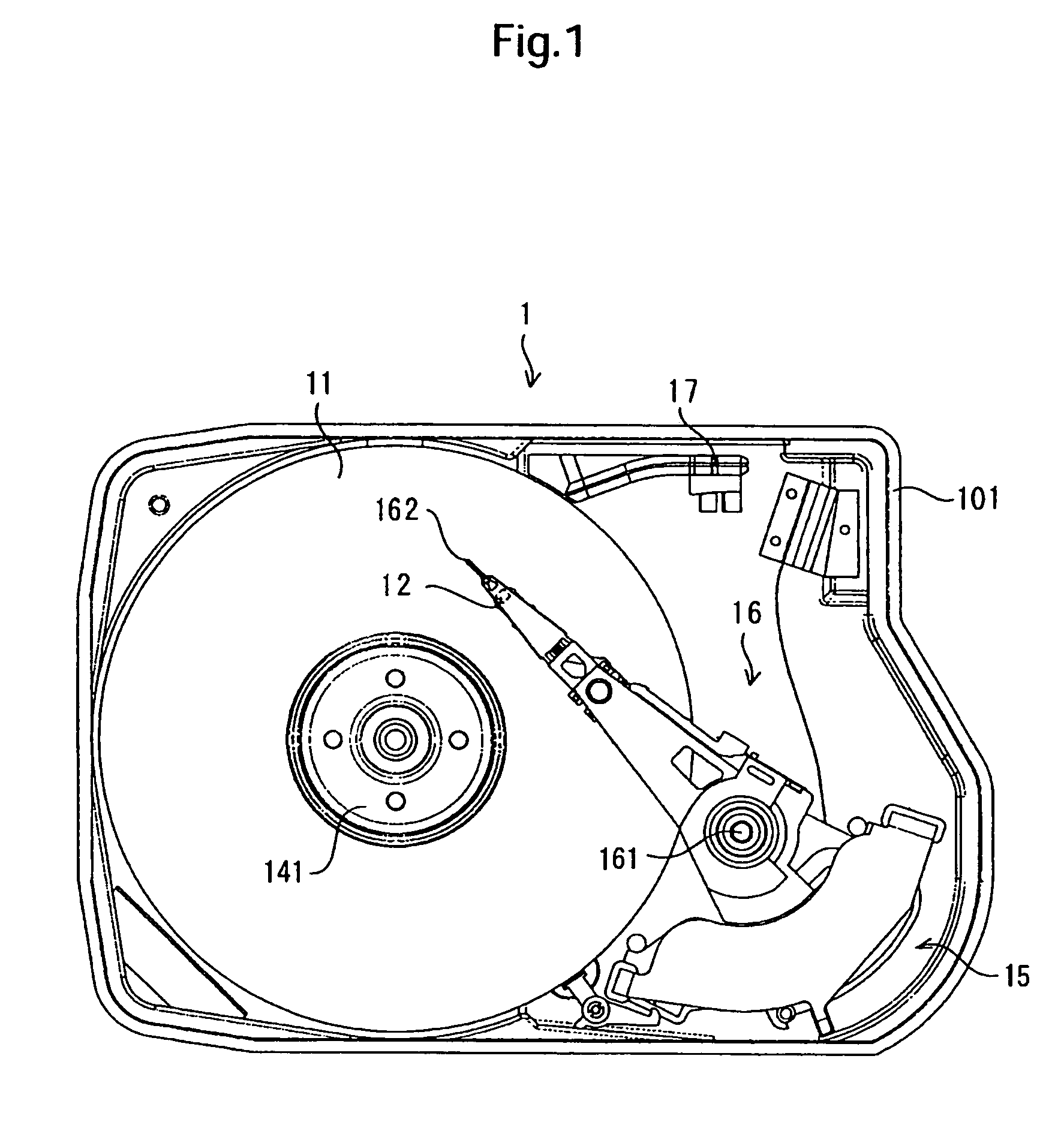
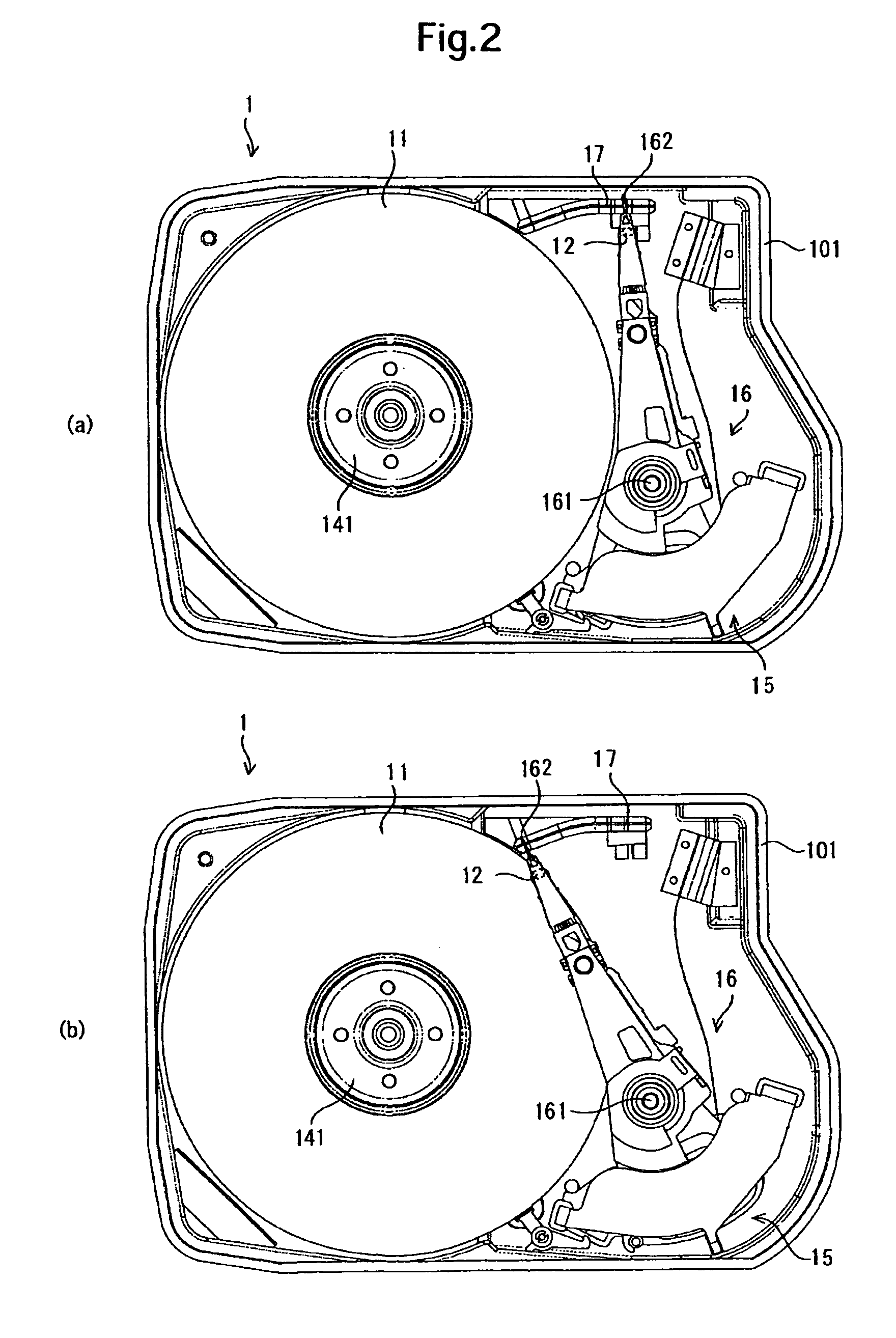
[0044]As an example of such a disk drive, a hard disk drive (HDD) embodiment is assumed in the following description of the present invention. FIG. 1 schematically shows the configuration of the HDD 1 according to the ...


PUM

PropertyMeasurementUnit
thermal expansionaaaaaaaaaa
temperatureaaaaaaaaaa
recording densityaaaaaaaaaa

Abstract

Embodiments of the invention allow a heater to reduce the clearance between a head element section and the magnetic section while reducing the risk of collision between the head element section and the magnetic disk during load / unload. In one embodiment, an HDD judges whether a heater is ON or OFF after the load process is started. If the heater is found set to ON, the HDD sets the heater to OFF. With the heater kept OFF, the HDD starts the actuator pivoting. If the heater is found set to OFF, the HDD moves the actuator from the parking position to the magnetic disk with the heater kept OFF. Upon completion of the load process, the HDD goes to the subsequent process. Since the heater is OFF during load, the risk of collision between the head element section and the magnetic disk is reduced.

Description

CROSS-REFERENCES TO RELATED APPLICATIONS[0001]This application claims priority from Japanese Patent Application No. JP2005-268148, filed Sep. 15, 2005, the entire disclosure of which is incorporated herein by reference.BACKGROUND OF THE INVENTION[0002]The present invention relates to a disk drive and a control method of it and, in particular, concerns the control of a heater provided in the head slider to adjust the clearance between the head element section and the recording disk in the disk drive.[0003]As known, there are a variety of data storage devices which use different types of media such as optical disks, magnetic tapes, and semiconductor memories. Among them, the hard disk drive (HDD) has become so popular as to be one of the indispensable storage devices for today's computer systems. Further, not limited to computers, the hard disk drive is widening its range of applications more and more due to the superior characteristics. For example, HDDs are now used in moving pictur...

Claims


Application Information

Patent Timeline
Patent Type & Authority Patents(United States)
IPC IPC(8): G11B21/02
CPCG11B5/54G11B5/6064G11B5/6005
Inventor WADA, TOSHIAKIISHIBASHI, KAZUYUKITSUCHIMOTO, KAZUNARIOHZEKI, HIDEKI
Owner HITACHI GLOBAL STORAGE TECH NETHERLANDS BV
Why Eureka
Try Eureka