Fixing apparatus and an image formation apparatus

a technology of fixing apparatus and fixing roller, which is applied in the direction of lighting and heating apparatus, instruments, furniture, etc., can solve the problems of increasing the capacity increasing the wait time, and greatly fluctuating the temperature so as to reduce the temperature drop of the fixing roller, the fixing quality is satisfactory, and the accuracy control

Active Publication Date: 2008-09-23
RICOH KK
View PDF13 Cites 10 Cited by
  • Summary
  • Abstract
  • Description
  • Claims
  • Application Information

AI Technical Summary

Benefits of technology

[0073]By providing two or more exothermic bodies with temperature detecting function in the longitudinal direction of the roller, the temperature distribution of the roller is accurately controlled, providing the fixing apparatus that is capable of fixing without hot offset or fixing defect.
[0074]By providing the auxiliary heater, the temperature can be quickly raised to the desired fixing temperature so that the fixing apparatus is capable of providing high-speed operations.
[0075]Further, by controlling the auxiliary heating unit based on the temperature detected by the exothermic body with temperature detecting function, the fixing apparatus is capable of providing both high-speed operations and satisfactory fixing quality.
[0076]By heating the recording paper, temperature drop of the roller is reduced, enabling the fixing apparatus to provide high-speed warm-up and high quality fixing without defects, especially where an operating-environment temperature is low.
[0077]By heating the pressurization roller, the fixing apparatus is capable of performing higher quality fixing without fixing defects.
[0078]By individually controlling power supply to the exothermic bodies with temperature detecting function according to the size (width) of the recording paper P, the fixing apparatus is capable of saving energy, avoiding useless power consumption.

Problems solved by technology

First, according to the heat roller method, the fixing roller has a great heat capacity, and for this reason, a quick start is not available. Further, if an elastic layer, such as silicone rubber, is provided on the fixing roller surface for improvement in speed and quality, the heat capacity is increased and the elastic layer surface has to be heated from the interior of the fixing roller. Accordingly, there is a problem in that wait time is prolonged.
However, according to the thermal fixing apparatus as described above, since the fixing roller uses the heat insulation elastic material, the heat capacity is less than that of the conventional the fixing roller used by the conventional fixing roller method, which poses a problem in that the fixing roller temperature greatly fluctuates while processing the recording paper.
Further, since a heating nip for heating the fixing roller 105 is arranged at the perimeter of the fixing roller 105, there is a problem in that changing the temperature of the fixing roller 105 is delayed, unlike in the case of on-demand fixing where heating is carried out at the fixing nip.
This poses a problem in that additional power is required.
Next, according to the film heating method, since the thin film having small heat capacity is used and the fixing nip is intensively heated, a quick start is possible; however, temperature control of the fixing nip is difficult.
Further, since the thin film is driven by the pressurization roller, film speed tends to be lower than the rotational speed of the pressurization roller, which poses a problem of degrading an image to be fixed.
Furthermore, there is also a problem called an “idle portion temperature rising” phenomenon with the fixing apparatus using the film heating method.
That is, when an exothermic body has an “idle portion” where the paper does not pass when printing on small size (width) paper, the “idle portion” is excessively heated, given that the exothermic body almost uniformly generates heat to the maximum paper width of the image formation apparatus, and that the heat is not dissipated by the paper at the “idle portion”.
Accordingly, when printing on small size paper such as an envelope, since the heat at the “idle portion” is not transferred to the paper, the temperature of the fixing apparatus is excessively raised.
Although this phenomenon is also a problem with the fixing apparatus of the conventional heat roller fixing method, the phenomenon is more of a problem with the fixing apparatus of the film heating method.
If the paper of a usual size (width being near the maximum paper width) is processed under this condition, since the temperature of the “idle portion” is excessively high, “hot offset” is produced in the portion corresponding to the small paper “idle portion”, degrading the printing quality.
However, the on-demand fixing apparatus of the film heating method is required to provide high speed printing; accordingly, lowering the throughput in order to solve the problem of “idle portion temperature rising” is not a desired solution.
However, it is conventionally impossible to prepare exothermic bodies corresponding to a great number of paper sizes, or to provide a thermistor to each part.
Further, since heat capacity of the fixing apparatus using the film heating method is small, the temperature has to be finely controlled according to the temperature of the pressurization roller.
Accordingly, when small size paper is passed, temperature rising at the “idle portion” is not properly detected.
Further, even if standard size paper is processed, both ends of the exothermic body tend to be cooled faster than central portions; therefore, there is often a difference between the temperature detected by the thermistor and the actual fixing temperature.

Method used


Image

  • Fixing apparatus and an image formation apparatus
  • Fixing apparatus and an image formation apparatus
  • Fixing apparatus and an image formation apparatus

Examples


Embodiment Construction

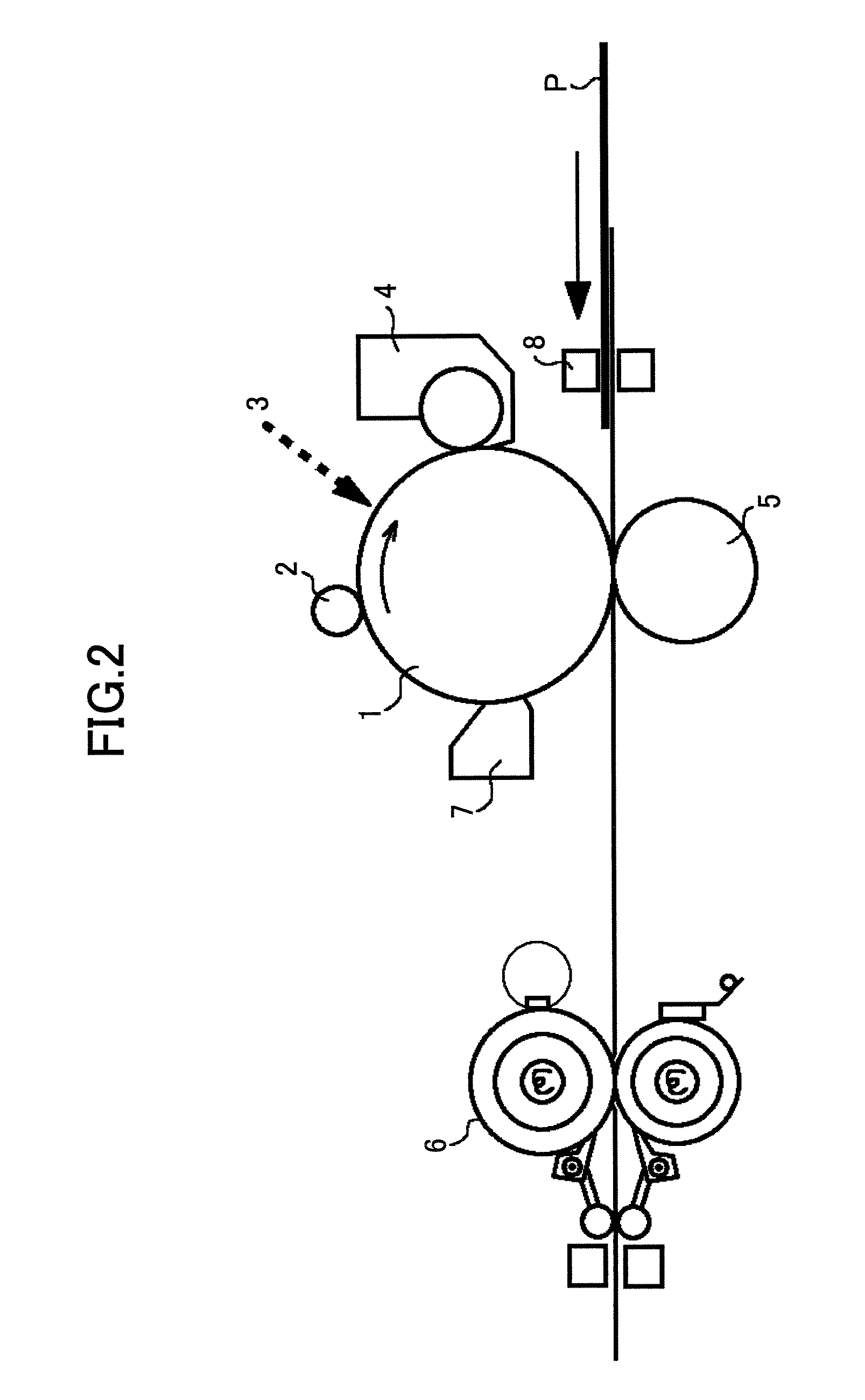
[0105]In the following, Embodiments of the present invention are described with reference to the accompanying drawings. First, an example of an image formation apparatus according to the present invention is described with reference to FIG. 2.

[0106]The image formation apparatus includes a photo conductor drum 1 serving as an image supporting object, where photo sensitive material, such as OPC, amorphous Se, and amorphous silicon, is formed on a base made of such as aluminum and nickel in the shape of a cylinder. The photo conductor drum 1 is rotationally driven in the direction of an arrow, and the surface of the photo conductor drum 1 is uniformly electrified (charged) by an electrification roller 2 serving as an electrification apparatus. Next, an electrostatic latent image is formed by scanning a laser beam 3 (optical system is not illustrated) that is turned on and off according to an image to be formed. The electrostatic latent image is developed and made visible by a developme...


PUM

PropertyMeasurementUnit
thicknessaaaaaaaaaa
thicknessaaaaaaaaaa
temperatureaaaaaaaaaa

Abstract

A fixing apparatus and an image formation apparatus are disclosed. The fixing apparatus includes two or more heaters with temperature detecting function that generate heat with electric current and detect temperature; a heating unit that includes the heater with the temperature detecting function; a film, a surface of which slides on the heating unit; a thermal fixing unit that is heated by the heating unit through the film for fusing a toner image that is yet-to-be fixed on a recording paper at a predetermined fixing temperature; a pressurization roller for pressing the recording paper to the thermal fixing unit; and a temperature control unit for controlling the temperature of the heater to be a predetermined temperature based on the temperature of the heater detected by the heater with the temperature detecting function.

Description

BACKGROUND OF THE INVENTION[0001]1. Field of the Invention[0002]The present invention relates to a fixing apparatus and an image formation apparatus.[0003]2. Description of the Related Art[0004]A fixing apparatus is used by an image formation apparatus that is included in, e.g., a copying machine, a printer, a facsimile apparatus, or a compound machine that has at least two of the above functions. The fixing apparatus, which is a thermal fixing apparatus, uses either a heat roller fixing method that provides a high thermal efficiency and safety using a contact-type heating roller, or a film heating method using an energy-saving type film.[0005]The thermal fixing apparatus using the heat roller fixing method includes a heating roller that rotates and is for heating (fixing roller), and an elastic pressurization roller that rotates and makes pressing contact with the fixing roller. The fixing roller and the pressurization roller form a pressing-contact nip (fixing nip). Through the ni...

Claims


Application Information

Patent Timeline
Patent Type & Authority Patents(United States)
IPC IPC(8): H05B1/00G03G15/20
CPCH05B3/0095
Inventor KOIDE, HIROSHIHATTORI, HITOSHIYASUI, MOTOKAZUFUJITA, TAKASHIIKENOUE, HIROKAZU
Owner RICOH KK
Why Eureka
Try Eureka