Phase detector and method providing rapid locking of delay-lock loops

a delay-locking loop and phase detector technology, applied in pulse generators, pulse techniques, digital transmission, etc., can solve the problems of time required, maintenance of permanent phase error between ssub>fb and fixed phase error, and disadvantage of allowing fixed phase error, so as to achieve the effect of quick locking condition

Active Publication Date: 2008-09-23
MICRON TECH INC
View PDF51 Cites 24 Cited by
  • Summary
  • Abstract
  • Description
  • Claims
  • Application Information

AI Technical Summary

Benefits of technology

[0013]A dual mode phase detector and method includes both a first phase detector and a second phase detector. The first phase detector generates at least one output signal indicative of the phase relationship between a first predetermined transition of a first input signal, such as its rising edge, and the first predetermined transition of a second input signal. The second phase detector generates at least one output signal indicative of both the phase relationship between the first predetermined transition of the first input signal and the first predetermined transition of the second input signal, and the phase relationship between a second predetermined transition of the first input signal, such as its falling edge, and the second predetermined transition of the second input signal. The dual mode phase detector also includes a selector that selects the at least one output signal from the first phase detector if the first and second input signals have a first phase relationship, and it selects the at least one output signal from the second phase detector if the first and second input signals have a second phase relationship that is different from the first phase relationship. The dual-mode phase detector may be used in a locked loop, such as a delay-locked loop. In such case, the dual edge phase detector is used to allow the loop to quickly achieve a locked condition. Thereafter, the single edge phase detector is used so that differences in the duty cycles of the first and second signals do not create fixed phase errors.

Problems solved by technology

Unfortunately, the phase of the system clock signal is normally substantially the same as the phase of the write data signals.
One limitation of the delay-lock loop 10 is the time required for the loop 10 to become “locked,” i.e., the phases of the SR and SFB signals substantially equaling each other.
Although a phase detector operating as shown in FIG. 3 has the advantage of allowing a locked loop to achieve faster lock time, it has the disadvantage of allowing a fixed phase error between the phase of the SR signal and the phase of the SFB signal in the event the duty cycle of either the SR signal or the SFB signal, as will now be explained with reference to FIG. 4.
The difference in the duty cycle of the SFB signal from the duty cycle of the SR signal thus results in the maintenance of a permanent phase error between the SFB and the SR signals.
As a result, the SOUT signal generated by the locked loop may not have the proper phase value.

Method used


Image

  • Phase detector and method providing rapid locking of delay-lock loops
  • Phase detector and method providing rapid locking of delay-lock loops
  • Phase detector and method providing rapid locking of delay-lock loops

Examples


Embodiment Construction

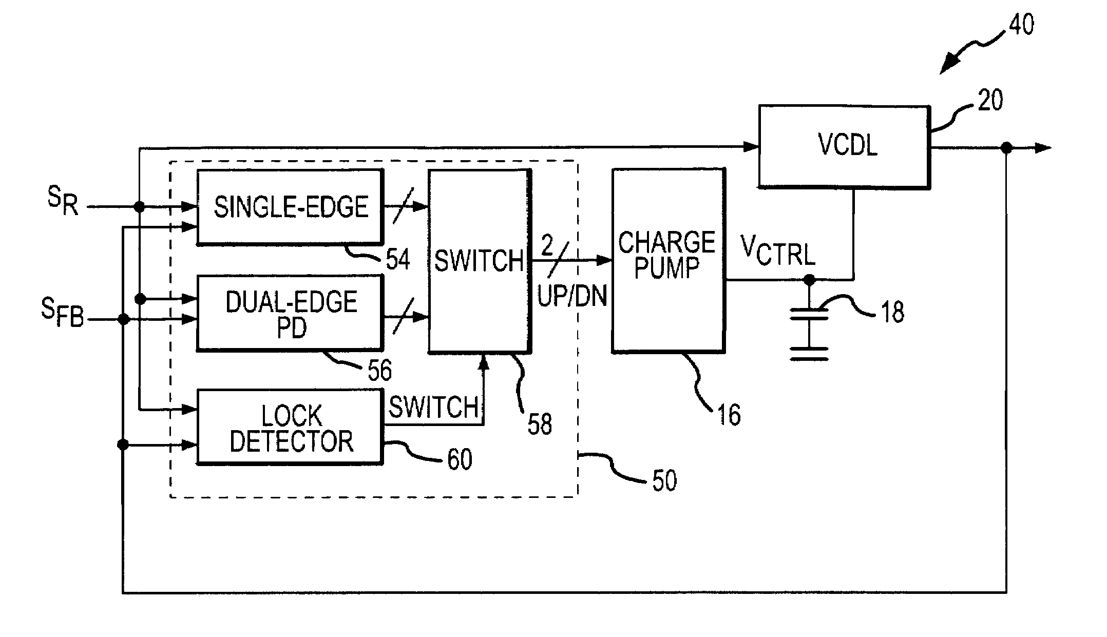
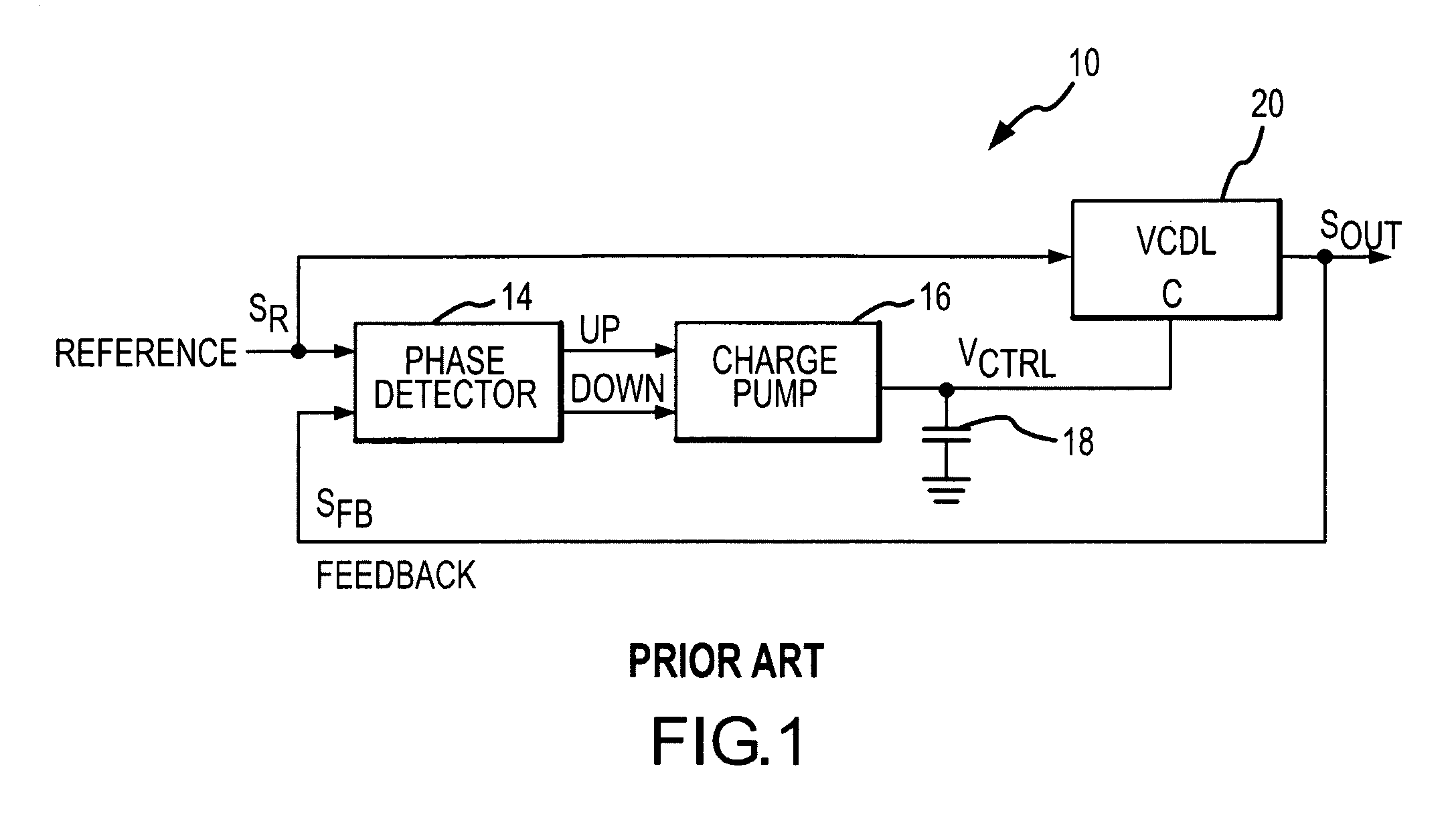
[0024]A delay-lock loop 40 according to one example of the present invention is shown in FIG. 5. The delay-lock loop 40 uses the same charge pump 16, capacitor 18 and VCDL 20 that are used in the delay-lock loop 10 of FIG. 1. These components operate in essentially the same manner in both loops 10, 40. Therefore, in the interests of brevity and clarity, an explanation of their function and operation will not be repeated.

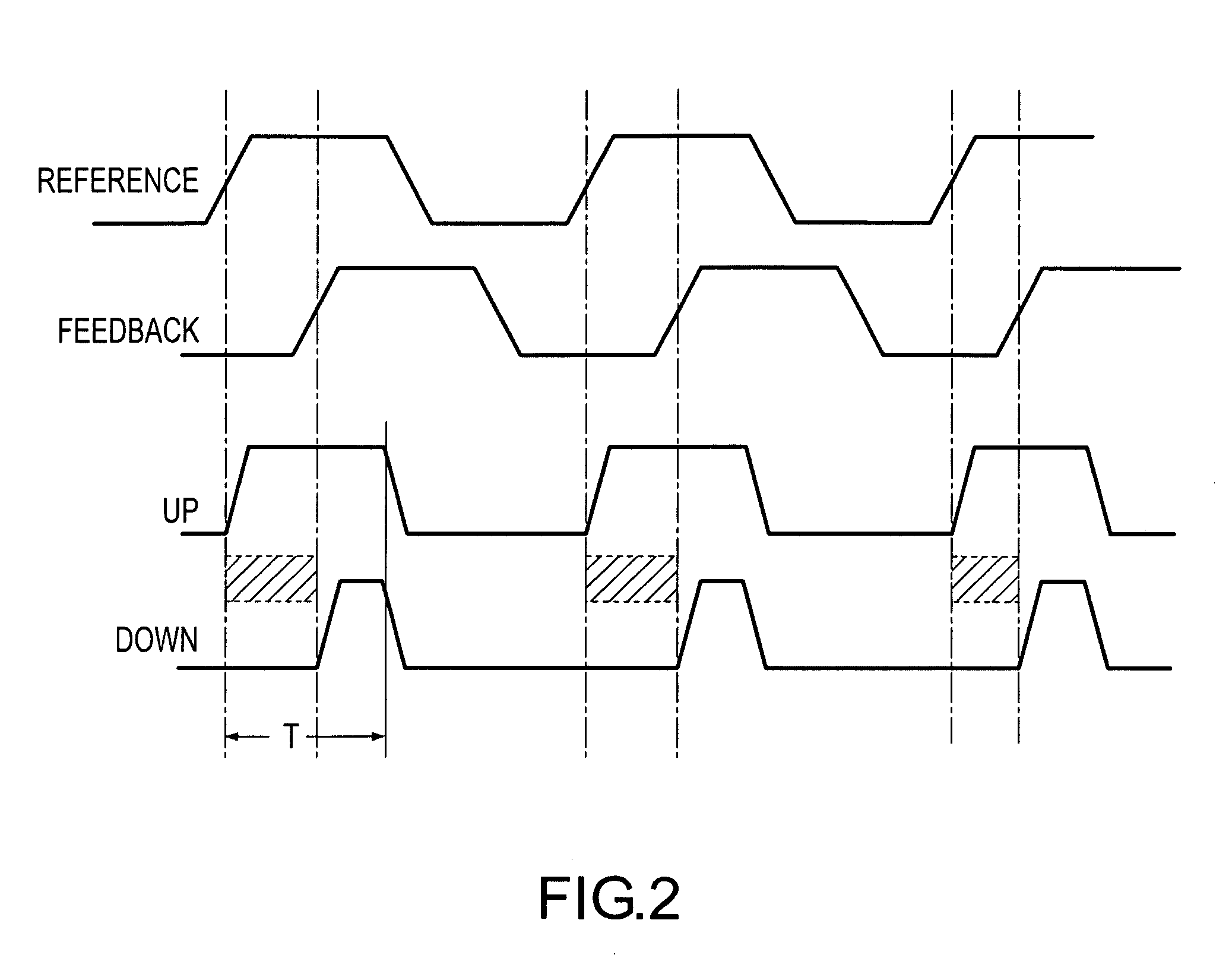
[0025]The delay-lock loop 40 differs from the delay-lock loop 10 of FIG. 1 in the use of a dual mode phase detector 50. The phase detector 50 includes both a single edge phase detector 54, which operates as shown in FIG. 2, and a dual edge phase detector 56, which operates as shown in FIGS. 3 and 4. Both of the phase detectors 54, 56 receive the reference signal SR and the feedback signal SFB, and they generate the “Up” and “Down” signals in response. The “Up” and “Down” signals are applied to respective inputs of a switch 58. The switch 58 selects the “Up” and “Down...


PUM


Abstract

A delay-lock loop includes a dual mode phase detector. The dual mode phase detector includes a single edge phase detector that generates output signals indicative of the phase relationship between the rising edge of a reference signal and the rising edge of a feedback signal generated by the delay-lock loop. The dual mode phase detector also includes a dual edge phase detector that generates output signals indicative of the phase relationship between both the rising edge of a reference signal and the rising edge of the feedback signal and the falling edge of a reference signal and the falling edge of the feedback signal. A lock detector controls a switch so that it couples the output signals from the single edge phase detector to a delay line when the loop is locked, and it otherwise couples the output signals from the dual edge phase detector to the delay line.

Description

TECHNICAL FIELD[0001]This invention relates to clock generating systems and methods, and, more particularly, to a phase detector that may be used in a delay-lock loop that operates in a manner that allows the loop to rapidly achieve a locked condition.BACKGROUND OF THE INVENTION[0002]Periodic digital signals are commonly used in a variety of electronic devices. Probably the most common type of periodic digital signals are clock signals that are typically used to establish the timing of a digital signal or the timing at which an operation is performed on a digital signal. For example, data signals are typically coupled to and from memory devices, such as synchronous dynamic random access memory (“SDRAM”) devices, in synchronism with a clock or data strobe signal. More specifically, read data signals are typically coupled from a memory device in synchronism with a read data strobe signal. The read data strobe signal typically has the same phase as the read data signals, and it is norm...

Claims


Application Information

Patent Timeline
Patent Type & Authority Patents(United States)
IPC IPC(8): H04L7/00
CPCH03D13/004
Inventor LIN, FENG
Owner MICRON TECH INC
Why Eureka
Try Eureka