Power distribution system for supplying a rail-mounted monument in an aircraft with electric power

a technology for distributing systems and monuments, which is applied in the direction of aircraft crew accommodation, coupling device connections, transportation and packaging, etc., can solve the problems of increasing fuel consumption, occupying additional space, and not providing the required stability, etc., and achieves the effect of simplifying the contact of the first conductor

Active Publication Date: 2008-09-30
AIRBUS OPERATIONS GMBH
View PDF12 Cites 15 Cited by
  • Summary
  • Abstract
  • Description
  • Claims
  • Application Information

AI Technical Summary

Benefits of technology

[0007]An electric potential relative to the surroundings can be advantageously realized in the seat rail and, in particular, in the first conductor. This electric potential can be tapped at any arbitrary location of the seat rail with the aid of the second conductor. The second conductor can be fixed in a certain position on the seat rail with the locking bolt and the clamping fixture and thusly secured from being displaced. This position can be chosen in increments of an inch-grid. Consequently, it is possible to apply a potential to a certain location along the seat rail without having to install a cable to this location. The potential can be applied to the respective location without having to provide cables that have an excess length and would unnecessarily increase the weight and the space requirement. The integration of the first conductor into the existing seat rail can reduce the space requirement. In addition, the installation time is reduced because it is not necessary to calculate any cable lengths. Changes of the installation position relative to the cables can be realized much easier because it is not necessary to install any new cables. This also increases the flexibility.
[0022]This may make it possible to remodel the cabin in a more flexible fashion and to continue using the power distribution system.

Problems solved by technology

Any element that is unnecessarily carried along in-flight increases the fuel consumption and occupies additional space.
However, electricity is only provided at a central location in an aircraft and consequently needs to be distributed to the respective consumers from this central location.
Since floor plates alone frequently do not provide the required stability, monuments that need to be solidly connected to a base, for example, seats, kitchens or toilets, cannot be arranged at arbitrary locations on the floor of the aircraft.
Since these cables should not be visible, they can usually not be installed along the shortest and most direct route, but rather need to be tediously concealed behind the paneling.
In addition, the position of the connecting points on the monuments is not always clearly defined such that the installed cables frequently have an “excess length” that increases the weight and the space requirement.
The required plug connectors can also lead to malfunctions and are frequently difficult to access.
This is the reason why their removal and, if applicable, repair is quite time-consuming.
It may also occur that it is neglected to separate the plug connectors when the monuments are removed.
This can result in plug connectors being torn off cables such that the corresponding repairs consume additional time.

Method used


Image

  • Power distribution system for supplying a rail-mounted monument in an aircraft with electric power
  • Power distribution system for supplying a rail-mounted monument in an aircraft with electric power
  • Power distribution system for supplying a rail-mounted monument in an aircraft with electric power

Examples


Embodiment Construction

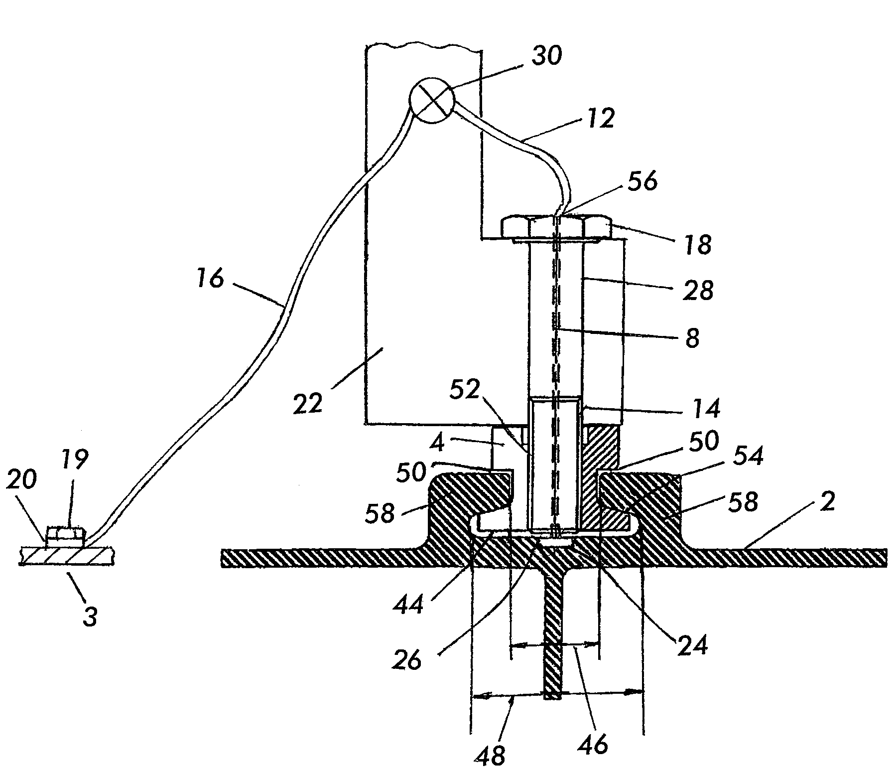
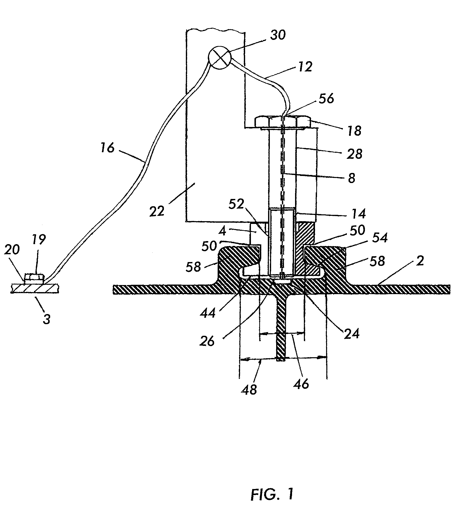
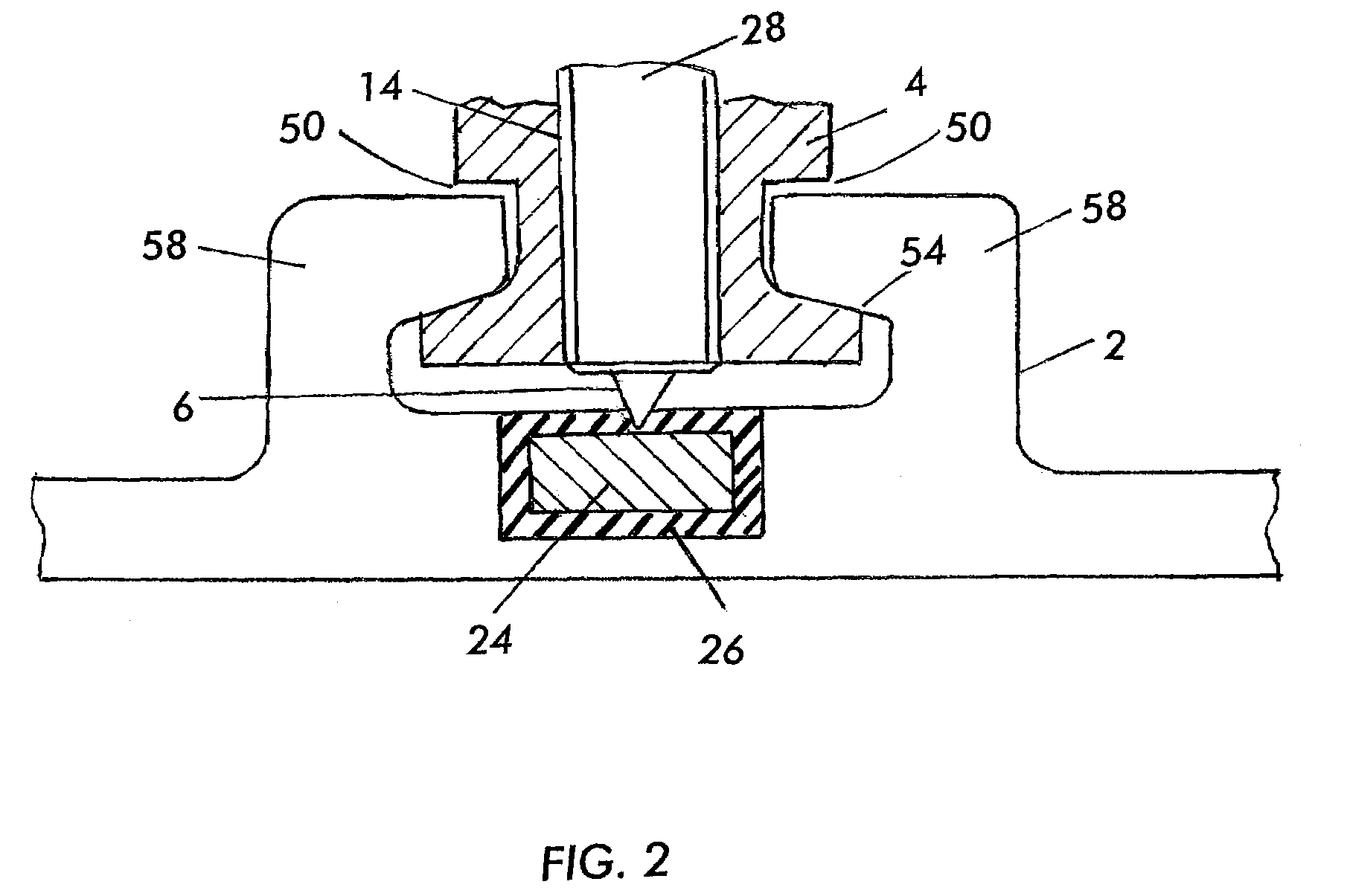
[0029]FIG. 1 shows a schematic section through a power distribution system according to an exemplary embodiment of the present invention. This figure shows how a monument 22 is mounted on a seat rail 2 by means of a locking bolt 28 and a clamping fixture 4. The seat rail 2 has a T-shaped profile. This T-shaped profile increases the stability and sufficiently strengthens the seat rail 2 for connecting a plurality of monuments 22. On its upper side, the seat rail 2 contains hook-shaped elevations 58 that are arranged centrally in a symmetric fashion and extend over the entire length of the seat rail that points into the plane of projection. The hook-shaped elevations 58 of the seat rail 2 define a T-shaped gap with a first dimension 48 and a second dimension 46, wherein the first dimension 48 is greater than the second dimension 46. The clamping fixture 4 has a rectangular cross section. The rectangular cross section is symmetrically interrupted on its sides by notches 50. Consequentl...


PUM


Abstract

The present application describes a power distribution system for supplying a rail-mounted monument in an aircraft with electric power. The power distribution system contains a seat rail that comprises an insulated first conductor, at which a current can be tapped with the aid of a locking bolt comprising a second conductor. The power distribution system simplifies the supply of electric power to a rail-mounted monument in an aircraft.

Description

REFERENCE TO RELATED APPLICATIONS[0001]This application claims the benefit of the filing date of U.S. Provisional Patent Application No. 60 / 600,922 filed Aug. 12, 2004, the disclosure of which is hereby incorporated herein by reference and the benefit of the filing date of German Patent Application No. 10 2004 039 189.0 filed Aug. 12, 2004, the disclosure of which is hereby incorporated herein by reference.FIELD OF THE INVENTION[0002]The present invention pertains to the power distribution in an aircraft. In particular, the present invention relates to a power distribution system for supplying a rail-mounted monument in an aircraft with electric power, a seat rail, a locking bolt, a clamping fixture, as well as a method for installing and removing a rail-mounted monument in an aircraft.BACKGROUND OF THE INVENTION[0003]In the construction of aircraft, a lightweight design is of the utmost importance. Any element that is unnecessarily carried along in-flight increases the fuel consump...

Claims


Application Information

Patent Timeline
Patent Type & Authority Patents(United States)
IPC IPC(8): H01R13/60
CPCB64C1/20B64D11/0696H01R4/2408B64D11/0624H02B1/205H02G5/04H01R25/14
Inventor HUEBER, STEFAN
Owner AIRBUS OPERATIONS GMBH
Why Eureka
Try Eureka