
Positioning method and positioning system based on light intensity

Active Publication Date: 2013-04-11
IND TECH RES INST
View PDF2 Cites 5 Cited by
  • Summary
  • Abstract
  • Description
  • Claims
  • Application Information

AI Technical Summary

Benefits of technology

The patent text describes a method and system for positioning a target using the intensity of light. A device is placed on the target to collect information about the light it receives from a lighting system. This information is used to calculate the position of the target. The location of the lighting system can then be adjusted accordingly to increase or match the needs of the target. The main technical effect of this method is to improve the accuracy of positioning in a way that is not affected by external factors such as wind or temperature.

Problems solved by technology

Nevertheless, since both the technique from indoor to outdoor and the technique from outdoor to indoor still have large errors and cannot compromise with the requirement of the precision, such that currently no indoor positioning system can be used by the mass.

Method used


Image

  • Positioning method and positioning system based on light intensity
  • Positioning method and positioning system based on light intensity
  • Positioning method and positioning system based on light intensity

Examples


case 1

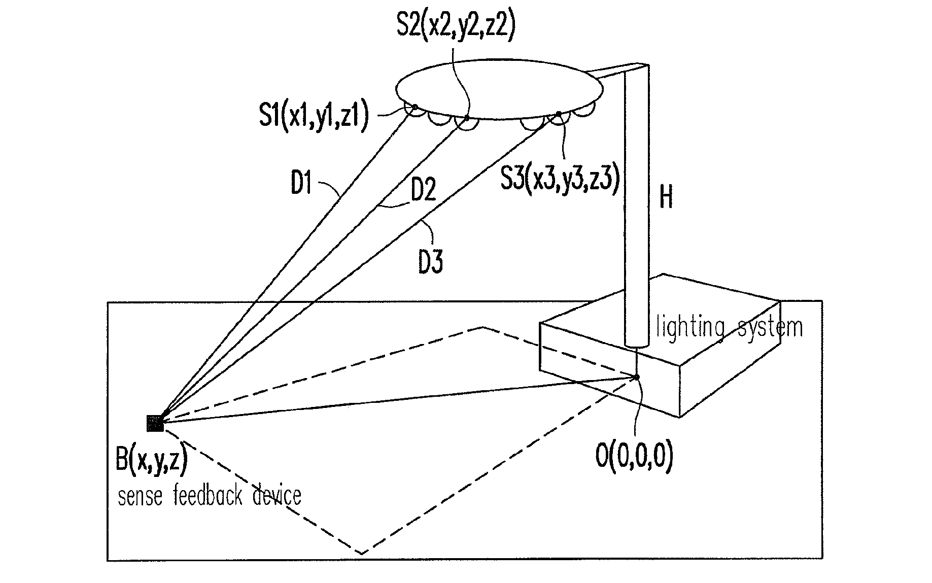
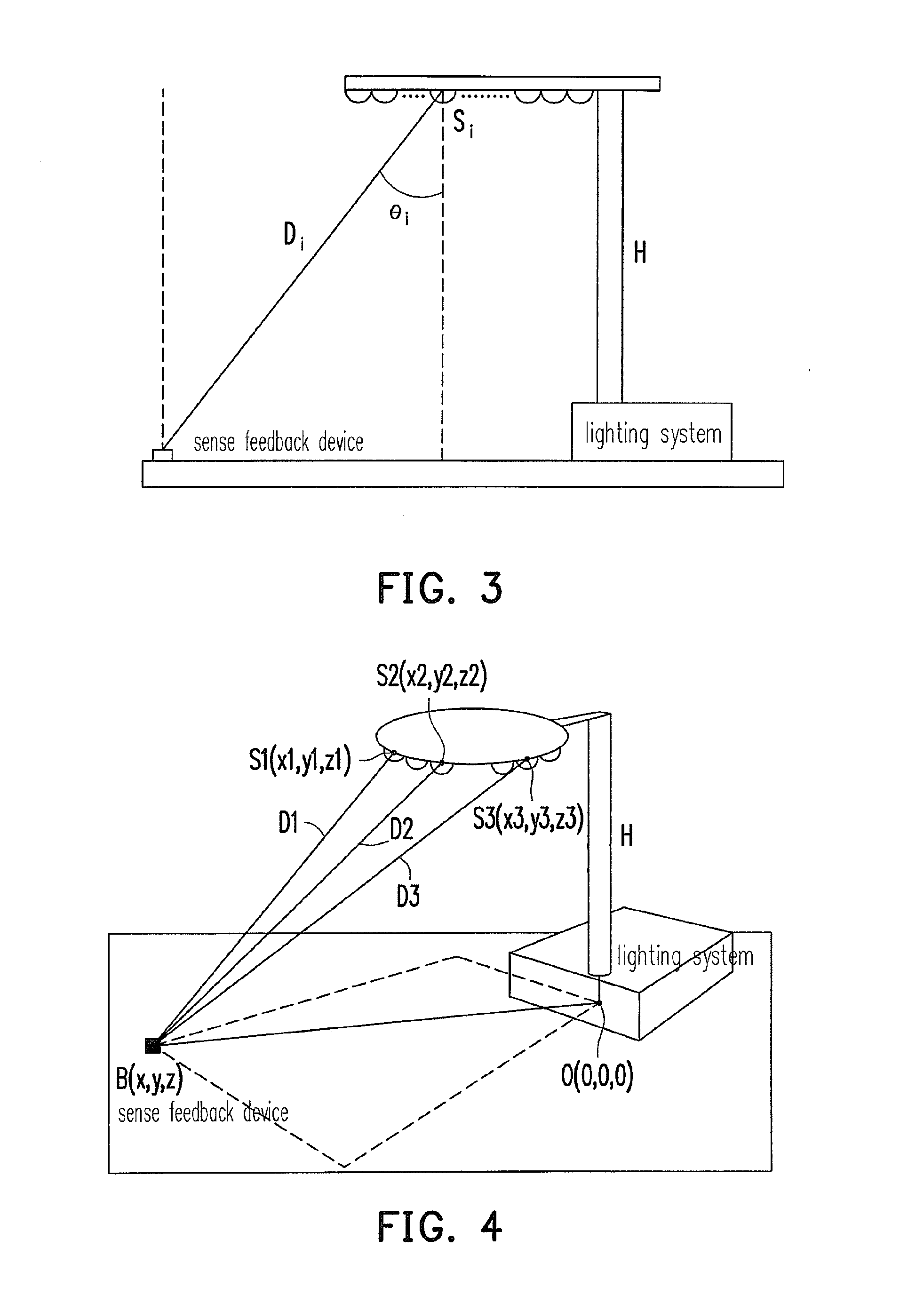
[0047] there is no intersection between the two equations. This is situation is impossible under this particular circumstance. Having no intersection would mean that the two spherical equations have no solutions. As long as there are light sources S1 and S2, the sensor on the target B(x, y, 0) can detect received light sources, and also mathematically there would be a solution to equations (7) and (8).

case 2

[0048] There is only 1 intersection between two spheres projected onto surface of z=0. If there is only 1 intersection, the correct position of target B can be calculated as one intersection means that there is only one solution for the two spherical equations.

case 3

[0049] There are two intersections between the two spherical equations projected onto the surface z=0. Two intersections mean that there are two solutions for the two spherical equations. When two circles are projected on the same z=0 surface, there cannot possibly be more than two intersections. Therefore, equations (7) and (8) would only have two possible solutions. When there are two solutions B1(xb1,yb1) and B2(xb2,yb2), these two solutions can be substituted back to equation (6) and solve for x and y as in B(x, y, 0) based on two equations and two unknowns. This works because as the light source S3 changes the light intensity, the target B(x, y, 0) would detect the change of light intensity. However, since one of the intersection between two circles would intersect on one side of the light sources at which the target B(x,y,z) is, the other solution would not be located at B(x, y, z). Therefore, even though there are two solutions or two intersections, only one of the intersecti...


PUM


Abstract

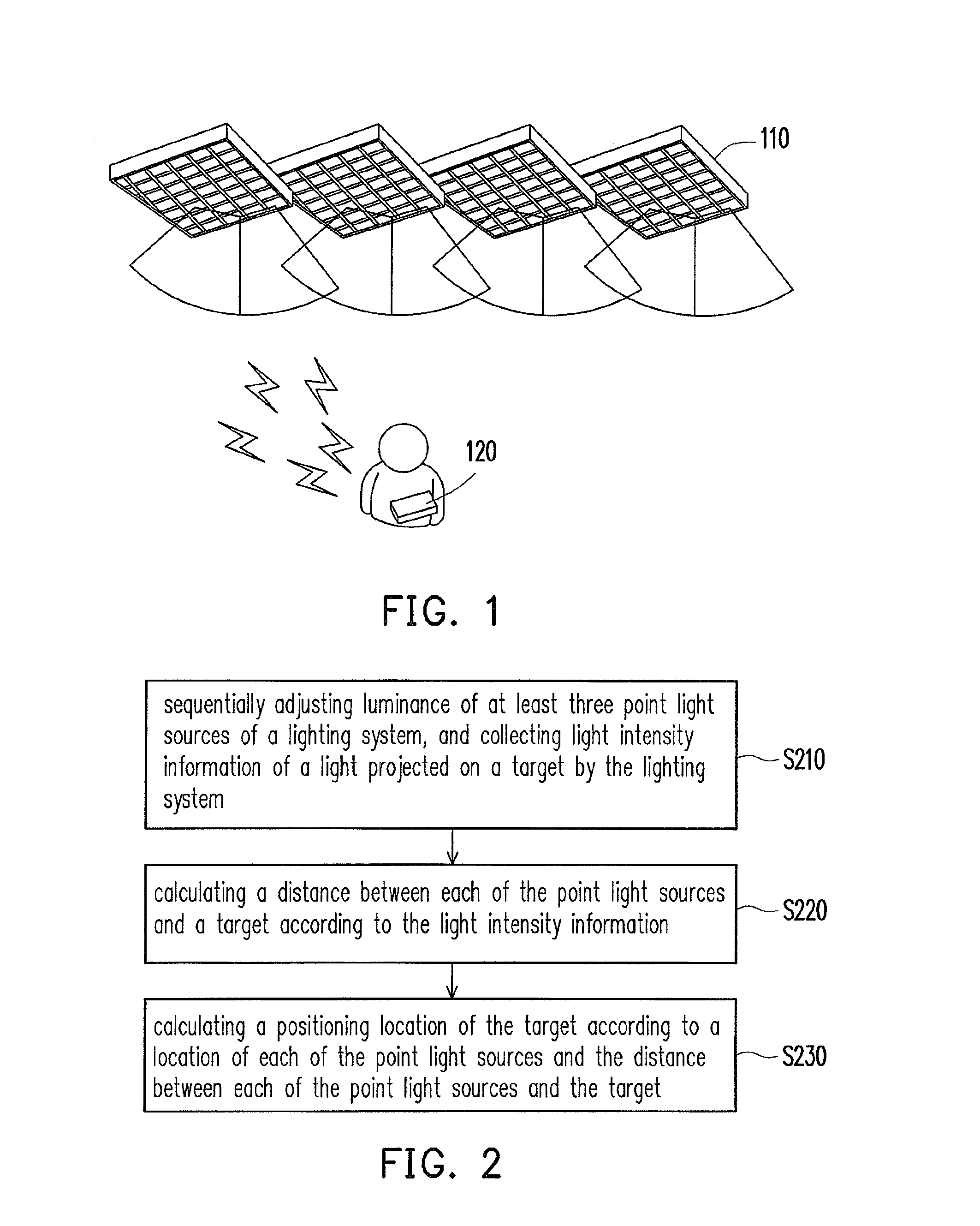
A positioning method and a positioning system based on light intensity are provided. The positioning system comprises a lighting system, a sense feedback device and a positioning module. The lighting system comprises at least three point light sources and sequentially adjusts luminance of these point light sources to light up a target. The sense feedback device is disposed on the target and used to collect light intensity information of the light projected on the target by the lighting system. The positioning module calculates a distance between the target and each of the point light sources based on the light intensity information and calculates a positioning location of the target based on the locations of the point light sources and the distances between the target and the point light sources.

Description

CROSS-REFERENCE TO RELATED APPLICATION[0001]This application is a continuation-in-part application of and claims the priority benefit of a prior application Ser. No. 12 / 469,677, filed on May 20, 2009, now pending. The prior application Ser. No. 12 / 469,677 claims the benefit of Taiwan application serial no. 98107346, filed on Mar. 6, 2009. The entirety of each of the above-mentioned patent applications is hereby incorporated by reference herein and made a part of this specification.TECHNICAL FIELD[0002]The disclosure relates to a positioning method and a positioning system based on light intensity.RELATED ART[0003]Currently, the positioning technique can be divided into two types, namely, outdoor positioning technique and indoor positioning technique. The most commonly used outdoor positioning technique is Global Position System (GPS). GPS has been extensively used in mobile device and can position the location of a person or a car in any place where a satellite signal can be receive...

Claims


Application Information

Patent Timeline
IPC IPC(8): G01B11/14
CPCG01S1/70G01S5/16G01B11/03G01B11/245G01C3/08G01S5/08G01S5/10
Inventor YEH, LUN-WULU, CHE-YENLEE, YUEH-FENGLIN, YU-HSUANTSENG, YU-CHEE
Owner IND TECH RES INST
Learn More