Backlight and liquid crystal display device

Inactive Publication Date: 2011-03-17
HITACHI CONSUMER ELECTRONICS CORP
View PDF4 Cites 2 Cited by
  • Summary
  • Abstract
  • Description
  • Claims
  • Application Information

AI Technical Summary

Benefits of technology

[0006]In recent years, from a point of view of a global warming problem, a requirement for energy-saving electrical equipment has been increased. Even in a liquid crystal display device such as a thin liquid crystal television (TV) and a display, reduction of entire power (set power) as a set of entire liquid crystal display device has been strongly required. A liquid crystal display device has a backlight, and a half or more of the set power becomes normally the power for the backlight. Therefore, it is effective to reduce the power for the backlight for reducing the set power.
[0007]In most cases, a cold cathode fluorescent lamp (CCFL) of one type of a fluorescent tube (lamp) is currently used as a light source for a backlight used for a liquid crystal display device. Since a narrow tube of 4 mmφ or smaller is used for the CCFL, the CCFL is advantageous for a thinned set resulted from a thinned backlight, and has an advantage of low cost per one tube. However, due to a largely-scaled (for example, 32 inch or larger) liquid crystal display (liquid crystal display device) such as a thin liquid crystal TV, a fluorescent tube length (bulb length) is increased. Due to increasing the fluorescent tube length in this manner, a driving voltage is increased higher, and therefore, it tends to complicate a lighting circuit for the CCFL and increase power consumption. Also, an input power per one tube is small, and therefore, it is required to increase the number of fluorescent tubes (bulbs) for ensuring screen brightness, and as result, there arise problems of increasing a component cost and the number of assembly processes.
[0010]A preferred aim of the present invention is to provide a backlight whose luminance efficiency (brightness efficiency) is improved by devising a structure of a HCFL to allow adjustment of a cold spot temperature, and provide a liquid crystal display device using the backlight.
[0016]By adjusting the cold spot temperature of the HCFL provided inside the backlight, the luminance efficiency (brightness efficiency) can be improved.

Problems solved by technology

Due to increasing the fluorescent tube length in this manner, a driving voltage is increased higher, and therefore, it tends to complicate a lighting circuit for the CCFL and increase power consumption.
Also, an input power per one tube is small, and therefore, it is required to increase the number of fluorescent tubes (bulbs) for ensuring screen brightness, and as result, there arise problems of increasing a component cost and the number of assembly processes.
In a conventional HCFL, the cold spot is formed in a center portion of the bulb (fluorescent tube), and the cold spot temperature is, for example, about 70° C. However, when the cold spot temperature is about 70° C., the luminance efficiency is not an optimum value, and therefore, there arises a problem incapable of sufficiently improving the luminance efficiency.
That is, in an existing HCFL, the cold spot is structurally formed in the center portion of the bulb (fluorescent tube), and the cold spot temperature cannot be set to a temperature resulting in the highest luminance efficiency (brightness efficiency), and therefore, there arises a problem incapable of sufficiently improving the luminance efficiency of the HCFL.
However, in the existing HCFL, the region where the cold spot is formed is in the center portion of the bulb (fluorescent tube), and therefore, it is difficult to adjust the temperature.
That is, for example, when it is considered that a radiator plate is provided so as to cover the center portion of the bulb (fluorescent tube) in order to decrease the temperature of the center portion of the bulb (fluorescent tube), the radiator plate shields light emitted from the center portion of the bulb (fluorescent tube), and therefore, there arises a problem of darkening a screen of the liquid crystal display device.
That is, in the center portion of the bulb (fluorescent tube) where the cold spot is formed, it is difficult to adjust the cold spot temperature.

Method used


Image

  • Backlight and liquid crystal display device
  • Backlight and liquid crystal display device
  • Backlight and liquid crystal display device

Examples


first embodiment

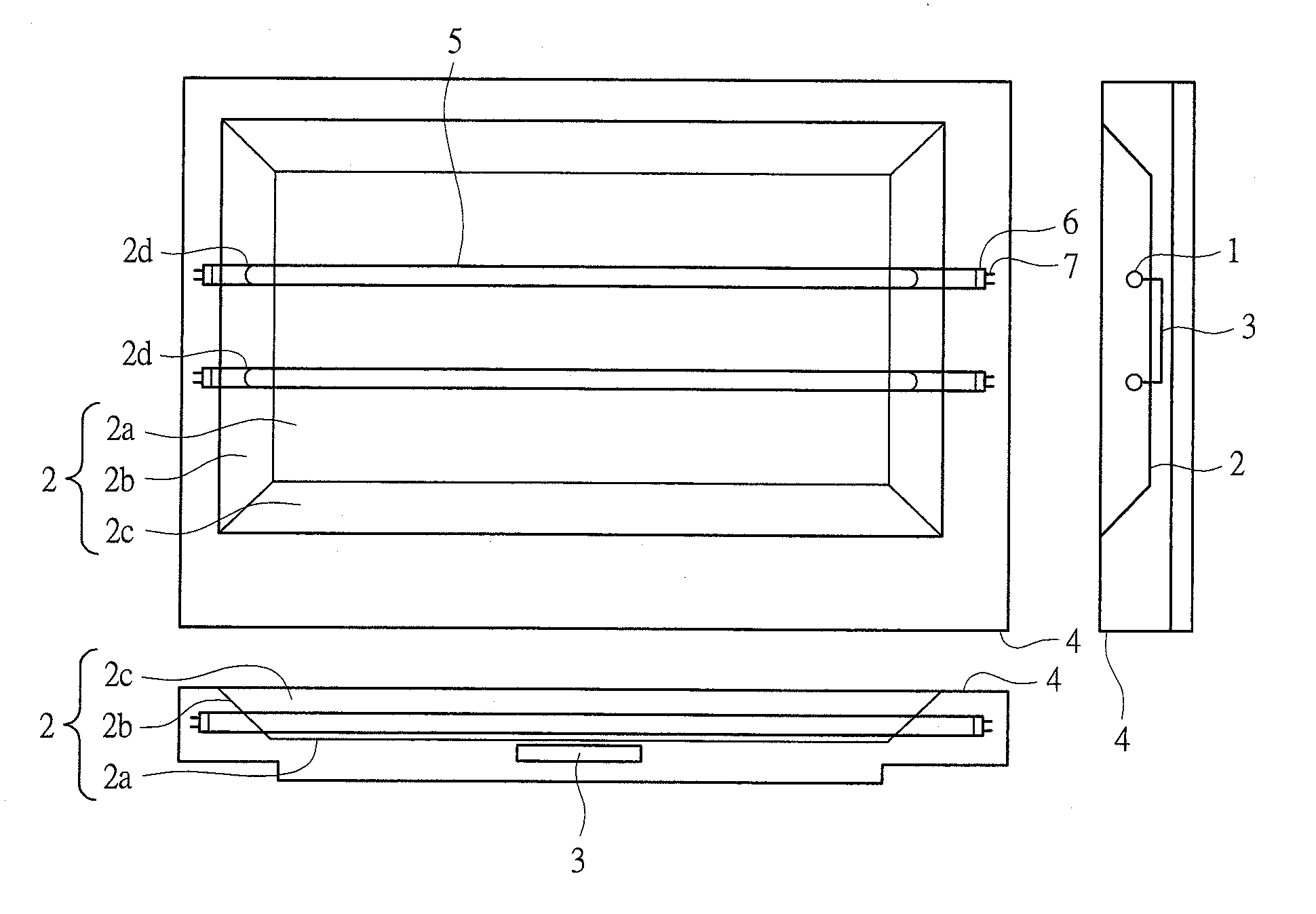
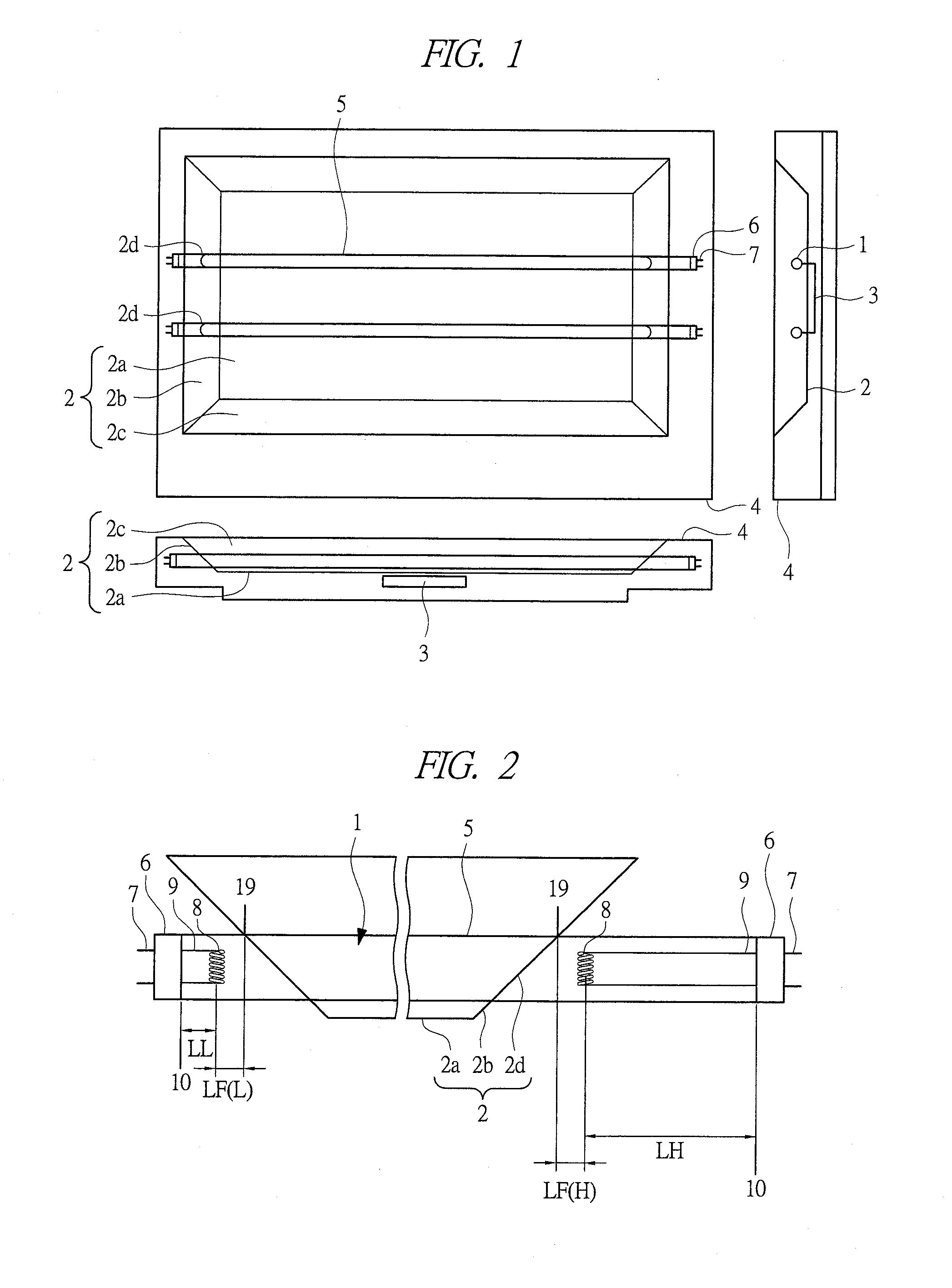
[0040]With reference to FIGS. 1 to 4, a first embodiment according to the present invention is described with using a backlight used for a 32-inch liquid crystal television (one type of a liquid crystal display device) as an example.

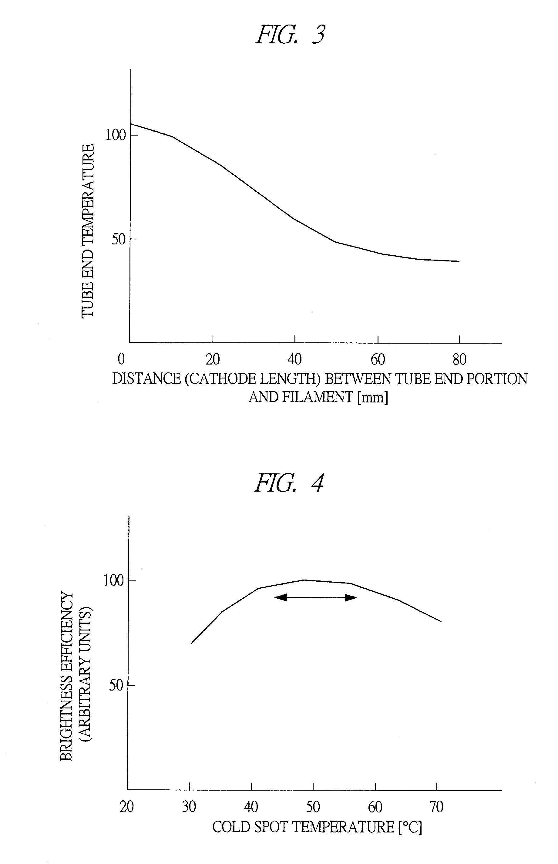
[0041]FIG. 1 is a view illustrating a schematic structure of the backlight used for the liquid crystal display device according to the first embodiment. FIG. 2 is a view illustrating a cross-sectional schematic structure of a hot cathode fluorescent tube 1 configuring the backlight according to the first embodiment. FIG. 3 is a graph illustrating a dependency of a tube end temperature of a tube end portion in the hot cathode fluorescent tube 1 with respect to a distance (cathode length) between the tube end portion of a bulb and a filament. FIG. 4 is a graph illustrating a dependency of brightness efficiency with respect to a cold spot temperature in a case that a longer cathode length of the hot cathode fluorescent tube 1 is 40 mm.

[0042]As illustrated i...

second embodiment

[0070]FIG. 5 is a view illustrating a schematic structure of a backlight used for a liquid crystal display device according to a second embodiment. Hereinafter, only different points from the first embodiment are described. Additional components to the schematic structure illustrated in FIG. 1 are: a vent (intake vent) 11a; a vent (exhaust vent) 11b; a partition plate 12; and a vent path 13. The vent (intake vent) 11a and the vent (exhaust vent) 11b are provided above and below the bottom cover 4, and the partition plate 12 is provided so as to fill a space between the bottom cover 4 and the reflective plate 2. The vent path 13 is a region surrounded by the bottom cover 4, the partition plate 12, the reflective-plate side surfaces 2b and 2c, vents 11a and 11b, and others. By providing the vent path 13, hot air caused by the heat radiated from the end portion of the hot cathode fluorescent tube 1 arranged from the reflective-plate side surface hole 2d toward the outside of the lamp h...

third embodiment

[0077]FIG. 8 is a view illustrating a schematic structure of a backlight used for a liquid crystal display device according to a third embodiment. In FIG. 8, a different point from the second embodiment is that a fan 16 is provided in a vicinity of the vent (exhaust vent) 11b. By the fan, the tube end portion 10 being the cold spot of the hot cathode fluorescent tube 1 can be further cooled. As a result, the cold spot temperature can be optimized, and therefore, the brightness efficiency of the hot cathode fluorescent lamp can be improved. Also, compared with the conventional technique, there is no cause of decreasing yield in the technique, and therefore, an effect of suppressing the decrease of the yield can be obtained. Note that, in FIG. 8, the fan 16 is provided in the vicinity of the vent (exhaust vent) 11b. However, a structure of the fan is not limited to this, and the fan 16 may be provided, for example, in a vicinity of the vent (intake vent) 11a, or in both of the vents 1...


PUM


Abstract

There are provided a backlight capable of improving luminance efficiency (brightness efficiency) by devising a structure of a HCFL to allow adjustment of a cold spot temperature, and further provided a liquid crystal display device using the backlight. A distance (cathode length) between one tube end portion and one filament of a pair of filaments is set longer than a distance (cathode length) between the other tube end portion and the other filament. In this manner, at least the tube end portion on the longer cathode length side can be set as the cold spot. Further, a tube end portion of a hot cathode fluorescent tube is arranged outside a lamp house. In this manner, the cold spot set at the tube end portion of the hot cathode fluorescent tube can be arranged outside the lamp house where the temperature is low, and the cold spot temperature can be decreased.

Description

CROSS-REFERENCE TO RELATED APPLICATION[0001]The present application claims priority from Japanese Patent Application No. 2009-213100 filed on Sep. 15, 2009, the content of which is hereby incorporated by reference into this application.TECHNICAL FIELD OF THE INVENTION[0002]The present invention relates to a backlight and a liquid crystal display device. More particularly, the present invention relates to a technique effective for improving luminance efficiency of the backlight.BACKGROUND OF THE INVENTION[0003]Japanese Patent Application Laid-Open Publication No. 2008-262818 (Patent Document 1) and Japanese Patent Application Laid-Open Publication (Translation of PCT application) No. 2008-504646 (Patent Document 2) disclose a technique of taking a cool action against a heat generation problem in a hot cathode fluorescent lamp (HCFL) used for a backlight of a liquid crystal display device.[0004]More specifically, Patent Document 1 exemplifies a backlight in which six hot cathode fluor...

Claims


Application Information

Patent Timeline
IPC IPC(8): G02F1/13357G09F13/08F21V29/505
CPCG02F1/133604G02F1/133611H01J61/523G02F2201/36G02F2001/133628G02F1/133628
Inventor YAMAMOTO, KENICHIMIKAMI, YOSHIROIMAMURA, SHINKATAGISHI, MAKOTO
Owner HITACHI CONSUMER ELECTRONICS CORP
Why Eureka
Try Eureka