Method and system for scribing brittle material followed by chemical etching

Active Publication Date: 2016-07-14
ROFIN SINAR TECH
View PDF0 Cites 23 Cited by
  • Summary
  • Abstract
  • Description
  • Claims
  • Application Information

AI Technical Summary

Benefits of technology

[0026]the laser pulses are focused such that sufficient energy density is maintained within the transparent material to form a continuous laser filament therein without causing optical breakdown;
[0027]simultaneously forming the continuous laser filament within the transparent material and simultaneously forming a low-power laser beam to ablate the photoresist layer and the metal layer, the power of the filament-forming laser beam is reduced below the threshold for the simultaneous of the filament within and through t

Problems solved by technology

This process creates poor quality edges, microcracks, wide kerf width, and substantial debris that are major disadvantages in the lifetime, efficiency, quality, and reliability of the product, while also incurring additional cleaning and polishing steps.
The cost of de-ionized water to run the diamond scribers are more than the cost of ownership of the scriber and the technique is not environmentally friendly since water becomes contaminated and needs refining, which further adds to the production cost.
Unfortunately, known laser processing methods have disadvantages, particularly in transparent materials, such as slow processing speed, generation of cracks, contamination by ablation debris, and moderated sized kerf width.
Furthermore, thermal transport during the laser interaction can lead to large regions of collateral thermal damage (i.e. heat affected zone).
However, the aforementioned disadvantages cannot be eliminated due to the aggressive interactions inherent in this physical ablation process.
This is amply demonstrated by the failings of UV processing in certain LED applications where damage has driven the industry to focus on traditional scribe and break followed by etching to remove the damaged zones left over from the ablative scribe or the diamond scribe tool, depending upon the particular work-around technology employed.
However, in general, the machining of transparent m

Method used


Image

  • Method and system for scribing brittle material followed by chemical etching
  • Method and system for scribing brittle material followed by chemical etching
  • Method and system for scribing brittle material followed by chemical etching

Examples


Example

[0079]Embodiments of the disclosure will now be described by way of example only.

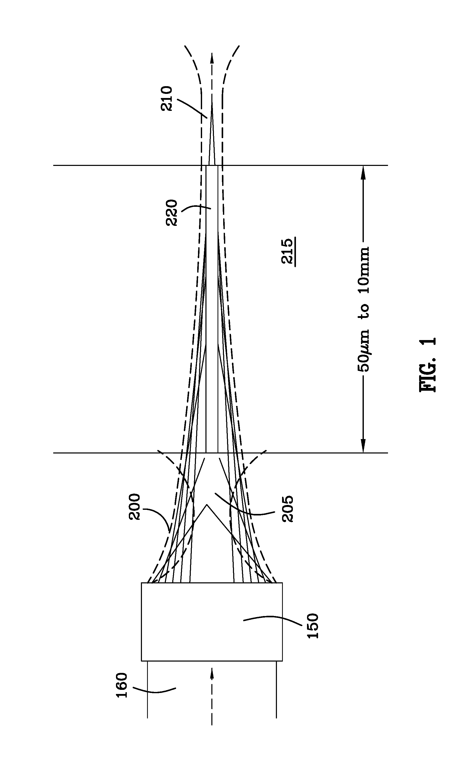
[0080]FIG. 1 illustrates optical configurations for the formation of filaments in which long homogeneous filaments 220 are formed by focusing the beam energy such that it is “dumped” into a focus above and / or below the transparent target material (forming an optical reservoir 220) in order to modulate the amount of energy passed into the desired filament zone. Incoming laser beam 160 passes through a distributed focus assembly 150 which creates foci above or below 210 the target substrate 215.

[0081]The propagation of ultrafast laser pulses in transparent optical media is complicated by the strong reshaping of the spatial and temporal profile of the laser pulse through a combined action of linear and nonlinear effects such as group-velocity dispersion (GVD), linear diffraction, self-phase modulation (SPM), self-focusing, multiphoton / tunnel ionization (MPI / TI) of electrons from the valence band to the con...


PUM

PropertyMeasurementUnit
Lengthaaaaaaaaaa
Pressureaaaaaaaaaa
Widthaaaaaaaaaa

Abstract

Very fine closed form structures can be scribed via filamentation in the transparent substrate very quickly, the modified zone can be etched via dry or wet chemical etching to release the closed form. A metal layer engages the transparent substrate and is covered with photoresist. A portion of the photoresist and a portion of the metal are removed simultaneously with the creation of a filament through the transparent substrate. The photoresist protects the portion of the metal layer that is not removed. The desired closed form can be released by weakening the cut region using dry or wet chemical etching to remove the desired part.

Description

[0001]This patent application claims the benefit and priority of U.S. provisional patent application Ser. No. 62 / 103,031 filed Jan. 13, 2015. U.S. provisional patent application Ser. No. 62 / 103,031 filed Jan. 13, 2015 is incorporated herein by reference hereto in its entirety.[0002]U.S. patent application Ser. No. 13 / 640,140, filed Jan. 31, 2013, U.S. patent application Ser. No. 14 / 336,912, filed Jul. 21, 2014, and U.S. patent application Ser. No. 14 / 336,819, filed Jul. 21, 2014 are hereby incorporated herein by reference hereto as if fully written herein.BACKGROUND OF THE INVENTION[0003]The present disclosure is related to systems and methods for the laser processing of materials. More particularly, the present disclosure is related to systems and methods for the singulation and / or cleaving of wafers, substrates, and plates containing passive or active electronic or electrical devices created upon said materials.[0004]In current manufacturing, the singulation, dicing, scribing, cle...

Claims


Application Information

Patent Timeline
IPC IPC(8): B23K26/402B23K26/362B23K26/0622G03F7/36
CPCB23K26/402B23K26/0622B23K26/362G03F7/36B23K26/364B23K26/0624B23K26/361B23K2103/50B23K2103/56B23K2103/54
Inventor HOSSEINI, S. ABBAS
Owner ROFIN SINAR TECH
Why Eureka
Try Eureka