Method of laser honing

a laser honing and laser technology, applied in the direction of manufacturing tools, metal working devices, welding/soldering/cutting articles, etc., can solve the problems of disc surface contact, lower tolerance in the manufacturing and operation of magnetic storage discs, and greater precision

Inactive Publication Date: 2008-01-03
SEAGATE TECH LLC
View PDF21 Cites 4 Cited by
  • Summary
  • Abstract
  • Description
  • Claims
  • Application Information

AI Technical Summary

Benefits of technology

[0011]This invention further relates to a method of finishing a surface of a workpiece, comprising providing a laser perpendicular to the surface, and focusing the laser onto or adjacent to the surface so that its energy density is sufficient for removing asperities that protrude from a surface without causing an undesirable amount of material to be removed from the surface.

Problems solved by technology

This trend has lead to greater precision and lower tolerance in the manufacturing and operating of magnetic storage discs.
A slight wobble or run-out in disc rotation can cause the surface of the disc to contact the read / write heads.
This is known as a “crash” and can damage the read / write heads and surface of the storage disc resulting in loss of data.
Further, electrochemical machining processes are known to leave sulfide inclusions protruding from the machined surface while eroding the surrounding metal, and processes such as grinding cause workpiece variation due to non-uniform yielding of the part and grinding wheel wear.

Method used


Image

  • Method of laser honing
  • Method of laser honing
  • Method of laser honing

Examples


Embodiment Construction

[0024]The following description is presented to enable a person of ordinary skill in the art to make and use various aspects and embodiments of the invention. Descriptions of specific materials, techniques, and applications are provided only as examples. Various modifications to the examples described herein will be readily apparent to those skilled in the art, and the general principles defined herein may be applied to other examples and applications without departing from the spirit and scope of the inventions.

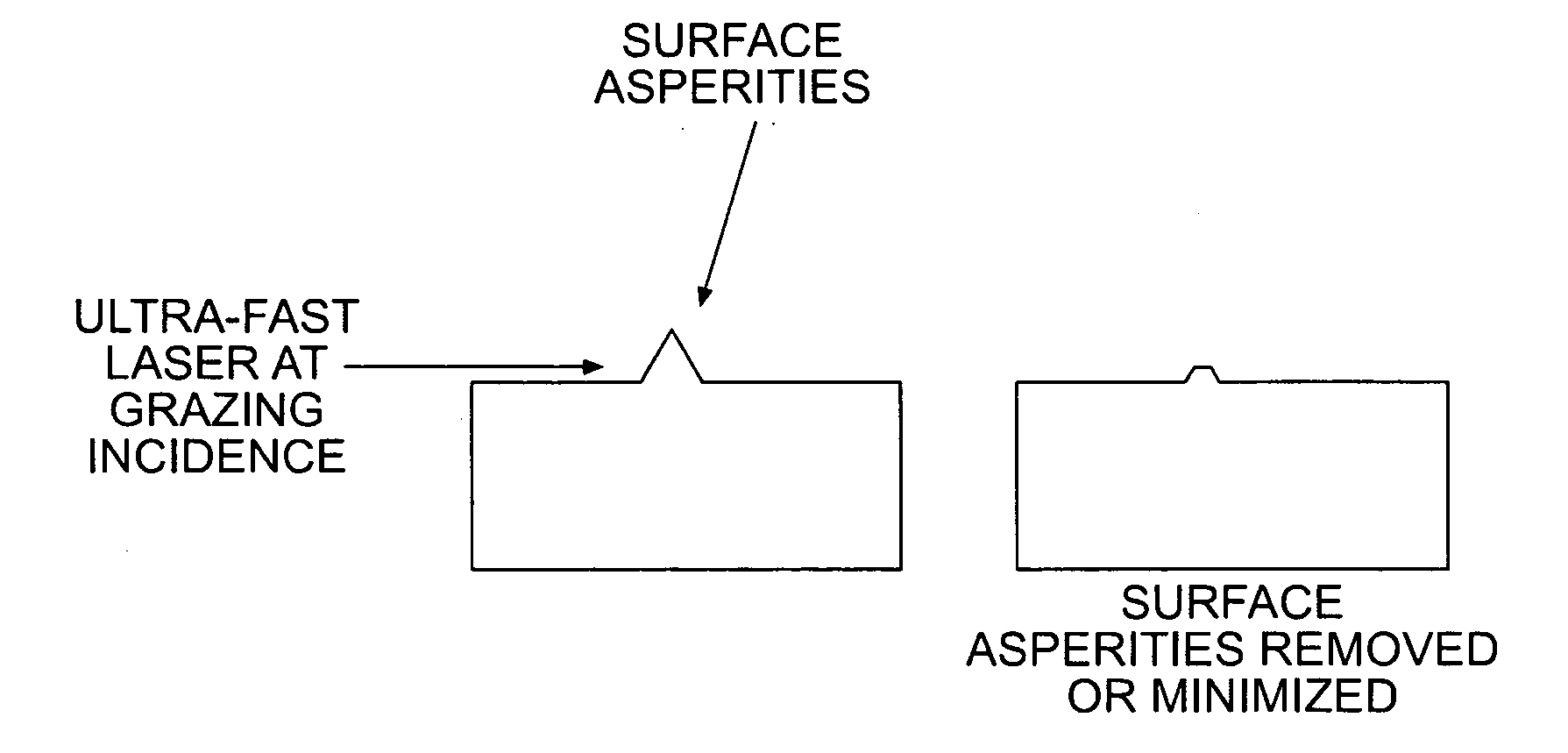
[0025]The present invention contemplates using a laser to remove machining marks left on the surface of workpieces. The laser is preferably directed incident to the surface of the workpiece, and particularly at a grazing incidence (along the surface of the workpiece). In a preferred embodiment, the laser is an ultra-fast pulse laser, allowing ablation of the machining marks, rather than melting. In a particularly preferred embodiment of the invention, the laser is a femtosec...


PUM

PropertyMeasurementUnit
energyaaaaaaaaaa
meltaaaaaaaaaa
energy densityaaaaaaaaaa

Abstract

A method of finishing a surface comprises providing a laser having a pulse shape and energy sufficient to remove asperities from the surface, and directing the laser at grazing incidence to the surface, so that it removes asperities from the surface.

Description

FIELD OF INVENTION[0001]The present invention relates generally to nano-machining with lasers to improve surface finish and form. This invention relates more specifically to nano-machining of component surfaces in spindle motors.BACKGROUND[0002]Magnetic discs with magnetizable media are used for data storage in most all computer systems. Current magnetic hard disc drives operate with the read-write heads only a few nanometers above the disc surface and at rather high speeds, typically a few meters per second.[0003]Generally, the discs are mounted on a spindle that is turned by a spindle motor to pass the surfaces of the discs under the read / write heads. The spindle motor generally includes a shaft fixed to a base plate and a hub, to which the spindle is attached, having a sleeve into which the shaft is inserted. Permanent magnets attached to the hub interact with a stator winding on the base plate to rotate the hub relative to the shaft. In order to facilitate rotation, one or more ...

Claims


Application Information

Patent Timeline
Patent Type & Authority Applications(United States)
IPC IPC(8): B23K26/36
CPCB23K26/0075B23K2201/36B23K26/365B23K26/0635B23K26/0624B23K26/3576B23K26/361B23K2101/36
Inventor SHETH, SANJAY C.LEE, JAMES S.
Owner SEAGATE TECH LLC
Why Eureka
Try Eureka