
Massaging device having controller to remove dead points during operation

a technology of dead points and massage devices, applied in the field of massage devices, can solve the problems of unsatisfactory massage patterns provided to different parts of the user's body, and achieve the effect of enhancing and pleasant massage

Inactive Publication Date: 2008-09-30
MATSUSHITA ELECTRIC WORKS LTD
View PDF34 Cites 21 Cited by
  • Summary
  • Abstract
  • Description
  • Claims
  • Application Information

AI Technical Summary

Benefits of technology

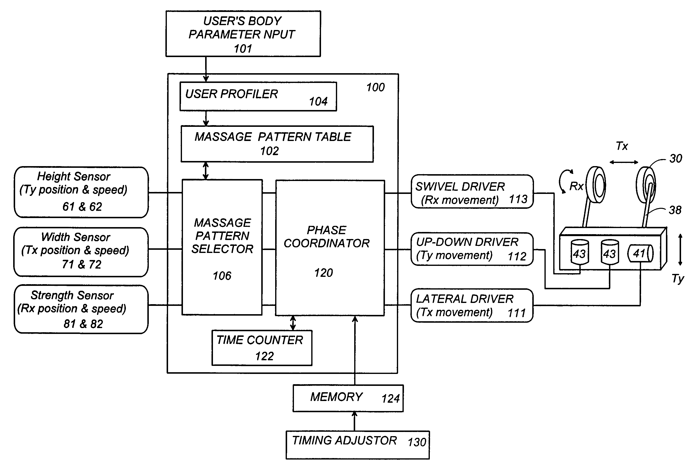
[0003]In view of the above problem, the present invention has been accomplished to provide a unique massaging device which is capable of applying different massaging patterns to different parts of the body for enhanced and pleasant massaging effect. The massaging device in accordance with the present invention includes a base, and an applicator movably supported to the base. The device includes at least two driving units which drive the applicator to make different reciprocating movements respectively in different directions from each other. A controller is included in the device to control the at least two driving units to reciprocate the applicator for providing a massaging force to a user in different massaging patterns. Also included in the device is at least one sensor which senses a position of the applicator relative to the base for acknowledging the position at which the applicator applies the massaging force. The important feature of the present invention resides in that a massage pattern selector is provided to select one of the massaging patterns depending upon the position of the applicator. Thus, the user can enjoy the different massage patterns for different parts of the body.
[0007]Further, the massaging device in accordance with the present invention has an advantageous feature of making the combined reciprocating movements to achieve a composite massaging action, yet in a seamless fashion, thereby giving smooth and pleasant massaging touch close to an expertise. For this purpose, the controller is designed to include a coordinator which shifts a dead point of one of the reciprocating movements relative to a dead point of another of the reciprocating movements. Thus, when the applicator is intended to make the combination of the two reciprocating movements, the applicator can be kept moving in one reciprocation cycle while it remains around the dead point of the other reciprocation cycle.
[0009]Further, the coordinator is arranged to monitor the phase of one of the reciprocating movements to detect a position of the applicator in the one movement. Based upon the detected position of the applicator, the coordinator shifts the phase of the other reciprocating movement relative to the phase of the one reciprocating movement by a time period in which the applicator moves to a predetermined position other than the dead point of its movement. Thus, the applicator can start moving away from the dead point in the one reciprocation cycle only after it reaches a position away from the dead point of the other reciprocation cycle. Accordingly, even if the applicator becomes temporality locked or stops due to a heavy load in one of the reciprocation cycle, the movement in the other reciprocation cycle can be shifted successfully and adequately only after the applicator advances actually to a predetermined position away from the dead point in the preceding reciprocation cycle, thereby avoiding concurrent rest of the applicator in both of the reciprocation cycles.
[0010]In addition, the device may include a timing adjustor which sets a variable time value which is added to the time period for varying the amount of the phase shift between the reciprocations. With the incorporation of the timing adjustor, the device can be well customized to give an optimum amount of the phase shift that the user can enjoy comfortable massaging effect. In this connection, the controller is preferably associated with a memory that stores the variable time set by the timing adjustor in order to hold the amount of the phase shift for enjoying the same massaging effect in a later use of the device.
[0011]The device may includes a pressure sensor which monitors a pressure being applied to the user's body by the applicator while the applicator makes one of said reciprocating movements. With the use of the pressure sensor, the coordinator can acknowledge the predetermined position of the applicator when the pressure sensor provides a particular output, which makes it easy to detect the actual position of the applicator in relation to the user's body.

Problems solved by technology

However, because of that the applicator is given only a single pattern of movement, i.e., a single massaging pattern, the device is found to be unsatisfactory for providing different massage patterns to different parts of the user's body.

Method used


Image

  • Massaging device having controller to remove dead points during operation
  • Massaging device having controller to remove dead points during operation
  • Massaging device having controller to remove dead points during operation

Examples


Embodiment Construction

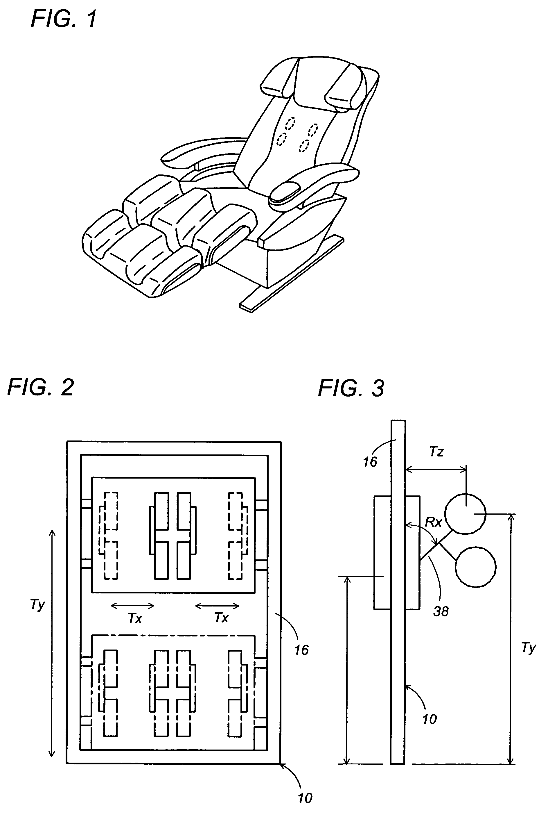
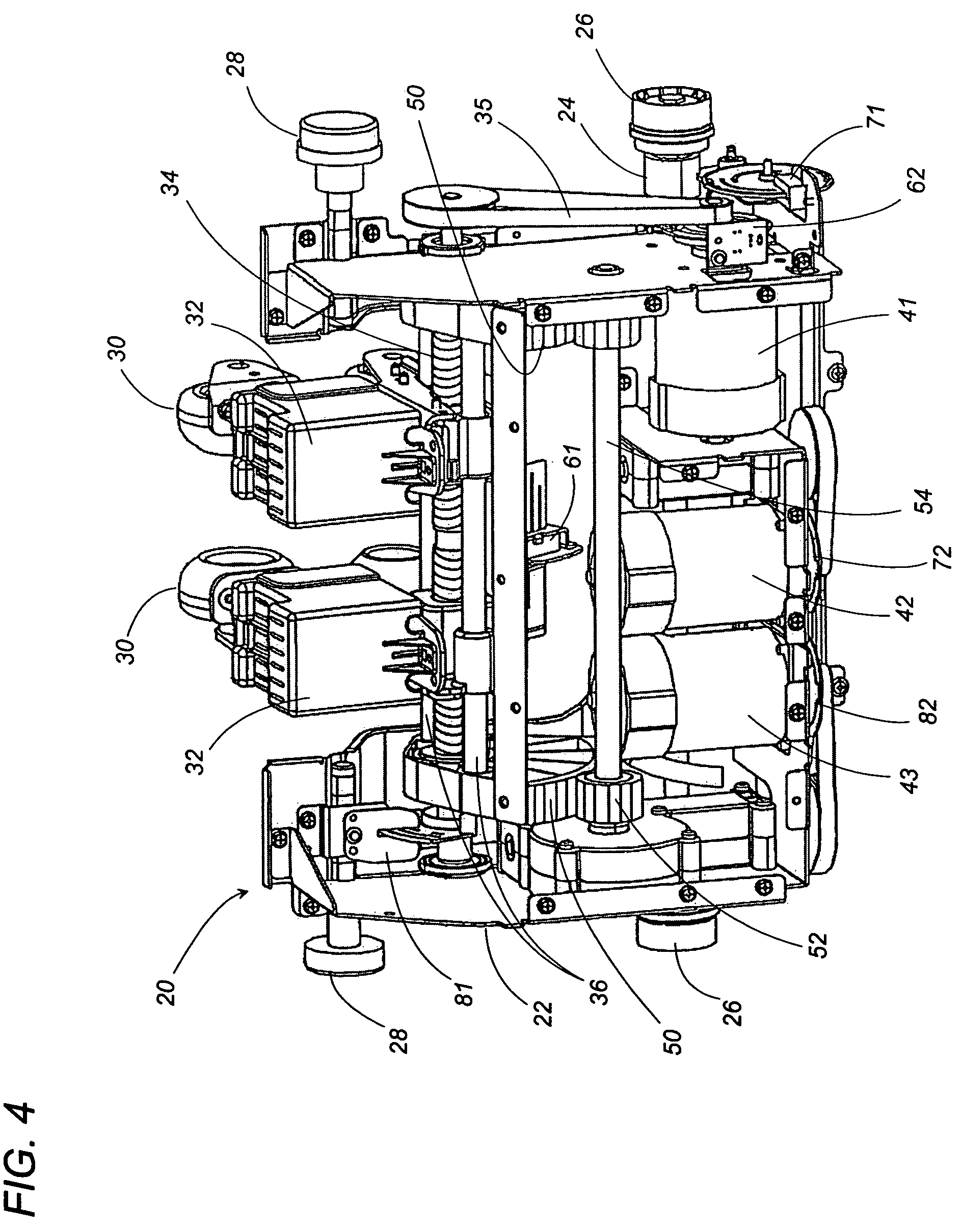
[0020]Referring to FIGS. 1 to 5, there is shown a massaging device in accordance with a preferred embodiment of the present invention. The massaging device is realized in the form of a chair having a framework or base 10 carrying an applicator module 20 embedded in a backrest 12 of the chair. The applicator module 20 is supported to the base 10 to be vertically movable along the length of the backrest 12. The applicator module 20 includes a pair of applicators 30 each composed of a set of vertically spaced rings which are supported to a cradle 32 so that, as will be discussed later in detail, the applicators 30 are movable relative to the module 20 along a lateral axis as well as about the axis X. As the module 20 itself is movable in the vertical direction relative to the base, the applicators are given three (3) degrees of freedom relative to the base 10, i.e., a lateral translational movement Tx along the lateral axis (X), a vertical translational movement Ty along the length (Y)...


PUM


Abstract

A massaging device gives different massaging patterns to different parts of a user's body for enhanced and pleasant massaging effect. The device includes an applicator applying a massage force to the user, and at least two driving units for driving the applicator to make different reciprocating movements respectively in different directions from each other. The least two driving units is controlled to reciprocate the applicator for providing the massaging force in different massaging patterns. A sensor is provided to acknowledge the position of the applicator. A massage pattern selector is provided to select one of the massaging patterns depending upon the position of the applicator.

Description

TECHNICAL FIELD[0001]The present invention relates to a massaging device, and more particularly to the massaging device that provides a composite massage action composed of forces acting in different directions from each other for realizing a sophisticated massaging effect close to human touch.BACKGROUND ART[0002]Japanese Patent Publication No. 5-137761 discloses a typical prior art massaging device in the form of a chair. The device includes an applicator which moves along the user's back to apply the massaging force to various parts of a user's body including shoulders, back, and waist. For generating the massaging force, the applicator is driven to give a cyclic movement or reciprocation along a predetermined path. The applicator is interlocked with the driving unit to reciprocate along a rather complicated path for applying effective massaging force to the user's body. However, because of that the applicator is given only a single pattern of movement, i.e., a single massaging pa...

Claims


Application Information

Patent Timeline
IPC IPC(8): A61H15/00A61H1/00A61H7/00A61H37/00
CPCA61H7/00A61H15/0078A61H7/007A61H2007/009A61H2201/0149A61H2201/1669A61H2201/1678A61H2201/1654A61H2205/04A61H2205/062A61H2205/081A61H2015/0028A61H2201/1623A61H2201/5007
Inventor TANIZAWA, TAKAYOSHIMIYAGUCHI, MASAMICHINISHIO, FUMIHIROTSUKADA, DAISUKENISHIBORI, YUUICHIMUTO, MOTOHARU
Owner MATSUSHITA ELECTRIC WORKS LTD
Learn More