Pipe liner connector

a technology of pipe liner and connector, which is applied in the direction of flexible pipes, rigid pipes, pipes, etc., can solve the problems of liner collapse, liner collapse and damage, and a significant number of pipe sections to pass a length of liner through

Inactive Publication Date: 2008-10-07
PIONEER LINING TECH
View PDF13 Cites 18 Cited by
  • Summary
  • Abstract
  • Description
  • Claims
  • Application Information

AI Technical Summary

Problems solved by technology

The primary restriction on the use of such liners is liner collapse due to pressure build up of gases in the micro-annulus between the liner and the parent pipe.
If the differential pressure between the micro-annulus and the pipe bore become sufficient, the liner may collapse and suffer damage.
This is a particular challenge where the method of jointing is to employ heat (such as welding) as the liner may be degraded during the process.
It is often problematic to pass a length of liner through a significant number of pipe sections.
However, this method has been found to be very expensive because it relies on high-cost corrosion resistant metallic components and time-consuming work methods.
The cost of providing the belled ends has been found to be prohibitive.
This method is also unsatisfactory to high-pressure applications because the cylindrical corrosion barriers contain voids of air and other compressible material between the face exposed to pressure and the wall of the host pipe.
The leak-tight seals at either side of the joint cause a differential pressure between these voids and the bore of the pipe giving rise to considerable expansion forces which cause it to deform uncontrollably, causing damage and distortion.
Increasing the thickness of the cylinder may resist this, but for high pressure applications, this imposes an unacceptable restriction on the bore of the pipe.
A further unsuitable aspect of sealed methods of bridging the joint in a liner occurs where gases may permeate or otherwise accumulate into the sealed spaces and voids between the cylindrical insert and the host pipe.

Method used


Image

  • Pipe liner connector
  • Pipe liner connector
  • Pipe liner connector

Examples


Embodiment Construction

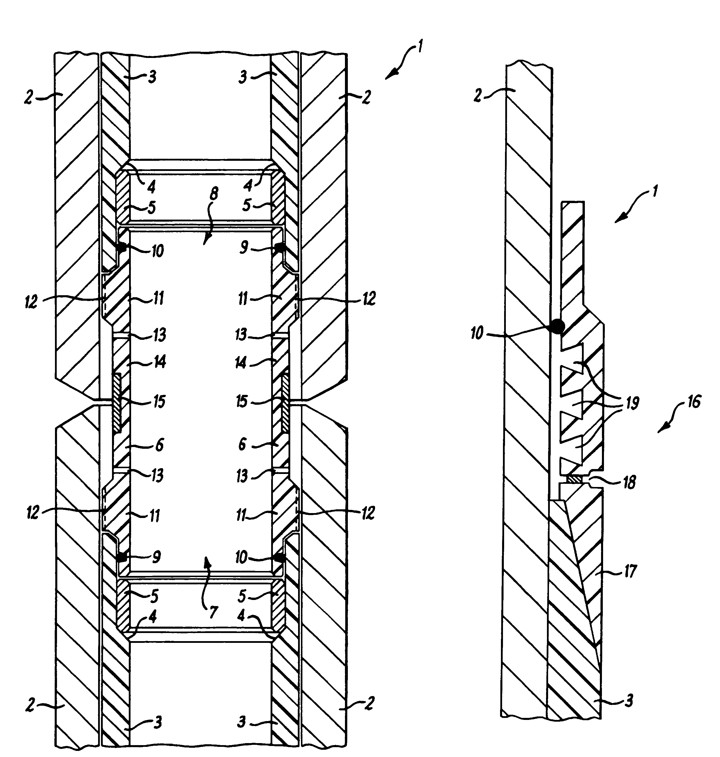
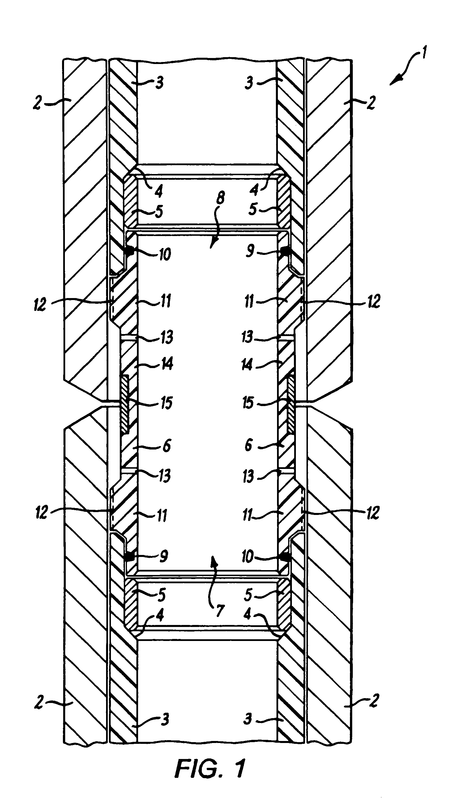
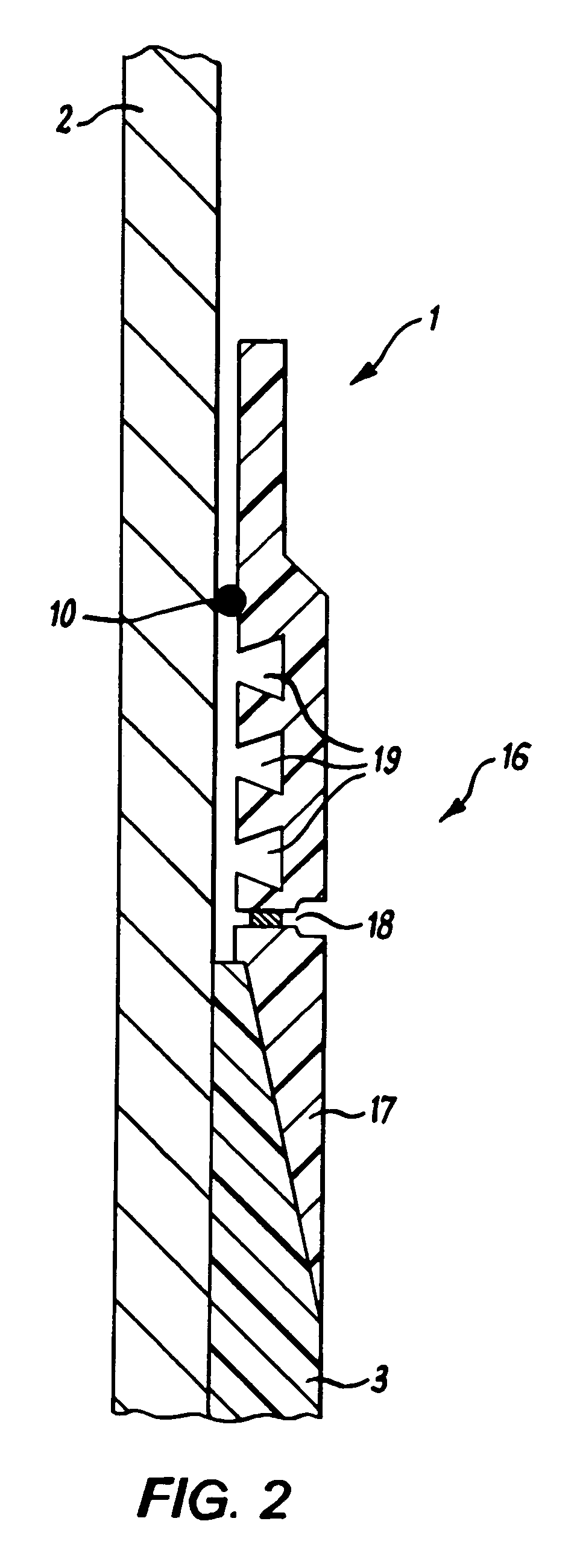
[0027]Referring to FIG. 1 a cross section of a pipe liner connector 1 is presented in conjunction with two pipe sections 2. Each pipe section 2 comprises a vented liner 3 that terminates with a cylindrical recess 4, of a greater internal diameter than that of the vented liner 3 itself. The cylindrical recesses 4 provide a means for locating the pipe liner connector 1 between two pipe sections 2, thereafter being fixed in position by the employment of locking rings 5.

[0028]The locking ring 5 is sized such that when it is inserted it squeezes the liner 3 tightly to the internal surface of the pipe section 2, holding it in place by a spring action and an associated compression in the liner 3. Alternatively, the locking ring comprises fixing screws (not shown) that adjust outwardly to compress the liner 3 to the internal surface of the pipe section 2.

[0029]The pipe liner connector 1 comprises a sleeve 6 that is generally in the form of a cylindrical tube having opposed open ends 7 and 8...


PUM


Abstract

A pipe liner connector suitable for connecting pipe sections that comprise a liner is described. The pipe liner connector comprise vents and / or venting grooves which act to balance the pressure between the micro-annulus, formed between the liner and the pipe sections, and the pipe bore formed when the pipe sections are connected together. The inclusion of these features helps prevent the collapse or the uncontrolled distortion of the pipe liner connector during pressure cycles in operating pipelines.

Description

CROSS-REFERENCE TO RELATED APPLICATION[0001]This application is the U.S. national phase, pursuant to 35 U.S.C. § 371, of international application No. PCT / GB2003 / 003272, published in English on Feb. 5, 2004 as international publication No. WO 2004 / 011840 A1, which claims the benefit of British application Ser. No. GB 0217274.0, filed Jul. 25, 2002, the disclosure of which applications are incorporated herein in their entireties by this reference.BACKGROUND OF THE INVENTION[0002]The present invention relates to apparatus for the connection of pipe liners. In particular, the apparatus provides a connector suitable for use with a liner employed in a vented oil, gas or other service pipeline.[0003]It is known to those skilled in the art that pipelines and other fluid transport systems (such as tubing used down-hole in oil wells and process pipework in refineries and the like) can have their lifetimes significantly increased by employing a liner. The liner is incorporated within the pipe...

Claims


Application Information

Patent Timeline
Patent Type & Authority Patents(United States)
IPC IPC(8): F16L11/12F16L13/02F16L55/165
CPCF16L13/0263F16L55/165
Inventor MCINTYRE, STUART
Owner PIONEER LINING TECH
Why Eureka
Try Eureka