Magnetic recording element and magnetic memory

a recording element and magnetic memory technology, applied in the field of magnetic recording elements and magnetic memory, can solve the problems of difficult magnetic field localization, inability to obtain magnetic field with enough magnitude for magnetization reversal, and difficulty in this techniqu

Active Publication Date: 2008-10-07
KIOXIA CORP
View PDF12 Cites 77 Cited by
  • Summary
  • Abstract
  • Description
  • Claims
  • Application Information

AI Technical Summary

Problems solved by technology

However, it is difficult for the magnetic field to be localized since the magnetic field has characteristics to diverge spatially.
Further, when attempting to achieve localization of the magnetic field by minimizing the generation source of the magnetic field, the magnetic field with enough magnitude for the magnetization reversal cannot be obtained.
However, there is a challenge in this technique as well.
Such a large value induces the problem of reliability such that element characteristic degradation.
However, when reducing the saturated magnetization Ms in conventional magnetic recording elements, new problems occur in which thermal fluctuation resistance and magnitude of the reproducing signal output deteriorate.

Method used


Image

  • Magnetic recording element and magnetic memory
  • Magnetic recording element and magnetic memory
  • Magnetic recording element and magnetic memory

Examples


first embodiment

(1) First Embodiment

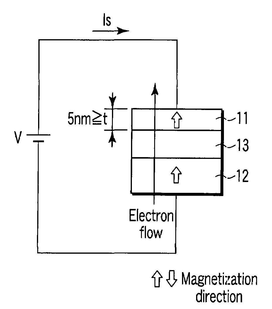
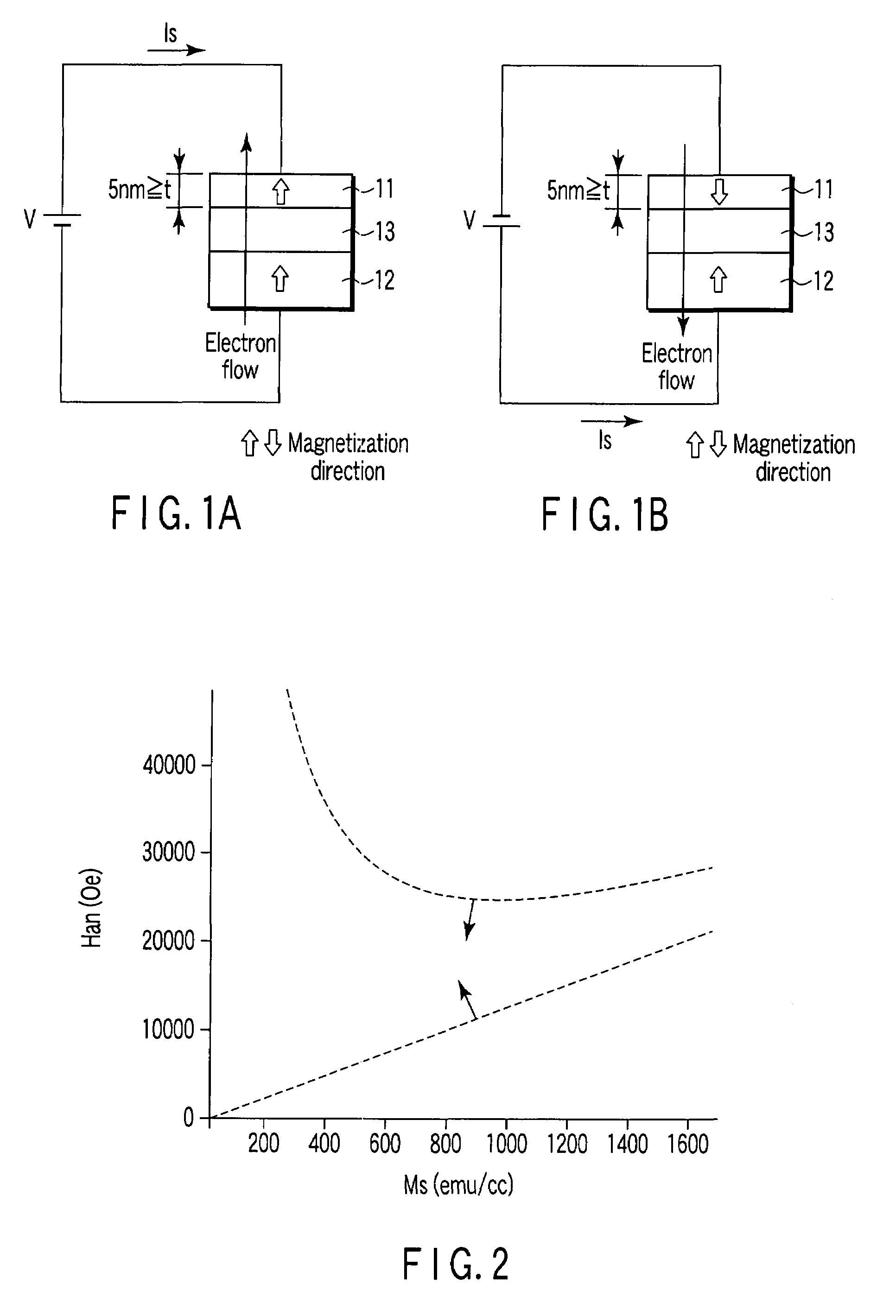
[0065]FIGS. 1A and 1B are side views showing a structure of a magnetic recording element of a first embodiment.

[0066]A magnetic free layer 11 has a variable magnetization, and a direction of easy axis of magnetization thereof is in a perpendicular direction to the film plane. A magnetic pinned layer 12 has a magnetization fixed in a direction perpendicular to the film plane. A non-magnetic barrier layer 13 is arranged between the magnetic free layer 11 and the magnetic pinned layer 12.

[0067]The magnetic free layer 11 is made of a magnetic material in which a relation between the saturated magnetization Ms (emu / cc) and the anisotropy field Han (Oe) satisfies Han>12.57 Ms and Han−1+12.57 Ms, and whose thickness is 5 nm or less.

[0068]The magnetic pinned layer 12 is constituted by the magnetic material. A magnetization direction of the magnetic pinned layer 12 is fixed because of, for instance, an anti-ferromagnetic layer. The non-magnetic barrier layer 13 is constit...

second embodiment

(2) Second Embodiment

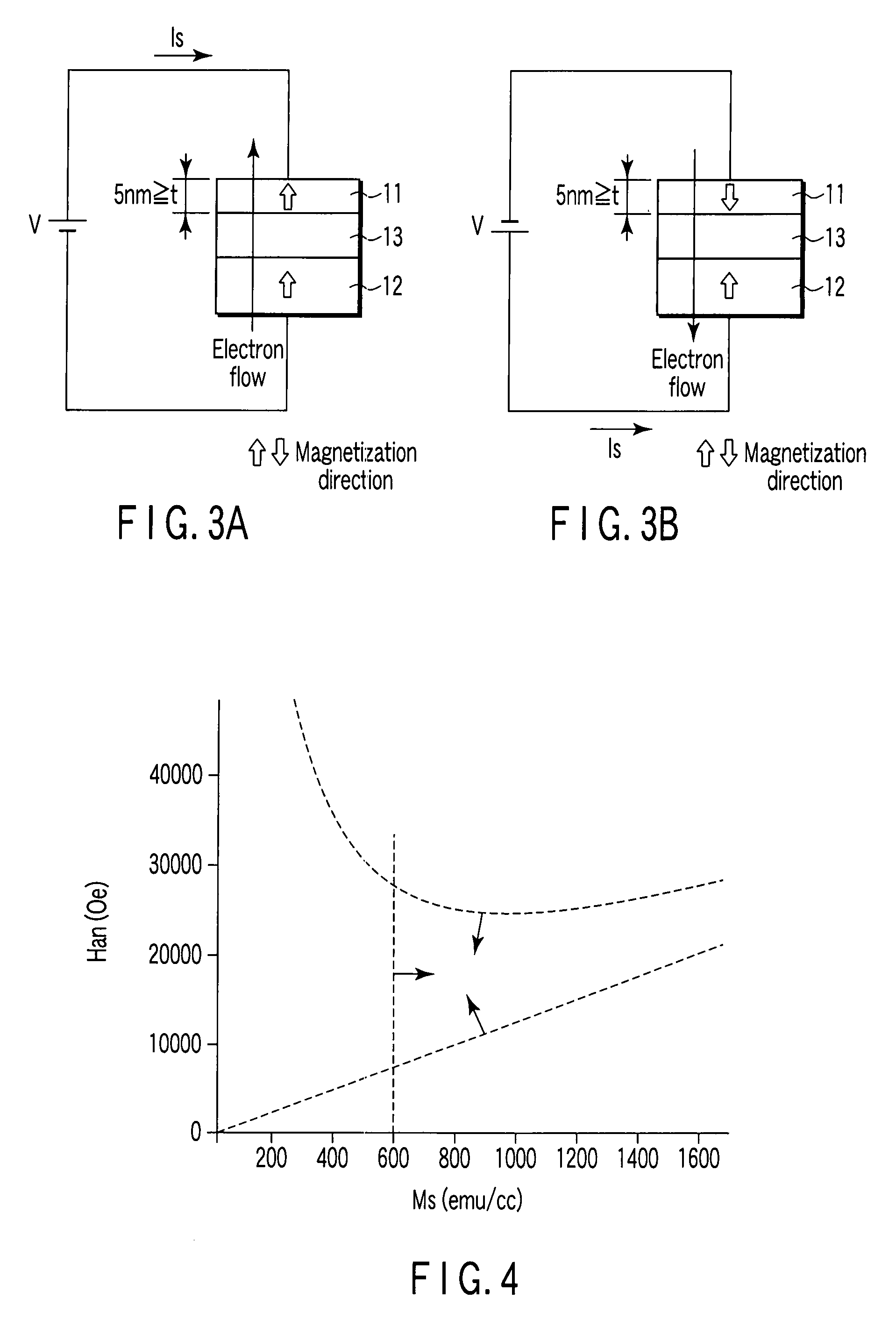
[0074]FIGS. 3A and 3B are side views showing a structure of a magnetic recording element of a second embodiment.

[0075]A magnetic free layer 11 has a variable magnetization, and a direction of easy axis of magnetization thereof is a perpendicular direction to the film plane. A magnetic pinned layer 12 has a magnetization fixed in a direction perpendicular to the film plane. A non-magnetic barrier layer 13 is arranged between the magnetic free layer 11 and the magnetic pinned layer 12.

[0076]The magnetic free layer 11 is made of a magnetic material in which a relation between the saturated magnetization Ms (emu / cc) and the anisotropy field Han (Oe) satisfies Han>12.57 Ms and Han−1+12.57 Ms, and whose thickness is 5 nm or less.

[0077]Further, the saturated magnetization Ms of the magnetic material constituting the magnetic free layer 11 is set to a value exceeding 600 emu / cc. This value is necessary to obtain an MR ratio 20% or more, the MR ratio being an index indic...

third embodiment

(3) Third Embodiment

[0084]FIGS. 5A and 5B are side views showing a structure of a magnetic recording element of a third embodiment.

[0085]A magnetic free layer 11 has a variable magnetization, and a direction of easy axis of magnetization thereof is a perpendicular direction to the film plane. A magnetic pinned layer 12 has a magnetization fixed in a direction perpendicular to the film plane. A non-magnetic barrier layer 13 is arranged between the magnetic free layer 11 and the magnetic pinned layer 12, and an insertion layer 14 is arranged between the magnetic free layer 11 and the non-magnetic barrier layer 13.

[0086]The magnetic free layer 11 is made of a magnetic material in which a relation between the saturated magnetization Ms (emu / cc) and the anisotropy field Han (Oe) satisfies Han>12.57 Ms and Han−1+12.57 Ms, and whose thickness is 5 nm or less.

[0087]Further, the insertion layer 14 is constituted by the magnetic material, and its saturated magnetization Ms is set to a value e...


PUM


Abstract

A magnetic recording element according to an example of the present invention includes a magnetic free layer whose magnetization is variable in accordance with a current direction passing through a film and whose direction of easy axis of magnetization is a direction perpendicular to a film plane, a magnetic pinned layer whose magnetization is fixed to a direction perpendicular to the film plane, and a non-magnetic barrier layer between the magnetic free layer and the magnetic pinned layer. In the magnetic free layer, a relation between a saturated magnetization Ms (emu / cc) and an anisotropy field Han (Oe) satisfies Han>12.57 Ms, and Han<1.2 E7 Ms−1+12.57 Ms.

Description

CROSS-REFERENCE TO RELATED APPLICATIONS[0001]This application is based upon and claims the benefit of priority from prior Japanese Patent Application No. 2006-092230, filed Mar. 29, 2006, the entire contents of which are incorporated herein by reference.BACKGROUND OF THE INVENTION[0002]1. Field of the Invention[0003]The present invention relates to a magnetic recording element and a magnetic memory utilizing a magnetization reversal by the spin-polarized electrons.[0004]2. Description of the Related Art[0005]In recent years, the research and development of spintronics devices by using the freedom degree of electron spins have been performed actively.[0006]For instance, in a hard disk drive, a magnetization state of a recording medium is controlled by a magnetic field from a magnetic head, while in a magnetic random access memory, a magnetic state of a magnetoresistive element is controlled by a composite magnetic field from two write lines.[0007]Such a method of controlling the magn...

Claims


Application Information

Patent Timeline
Patent Type & Authority Patents(United States)
IPC IPC(8): H01L29/06
CPCB82Y25/00G01R33/093G11C16/16H01F10/3227H01F10/3286H01L27/222H01L27/228H01L43/10H01F10/3254H10B61/00H10B61/22H10N50/85H10N50/10
Inventor NAKAMURA, SHIHOMORISE, HIROFUMI
Owner KIOXIA CORP
Why Eureka
Try Eureka