CPP giant magnetoresistive head including pinned magnetic layer that extends in the height direction

a giant magnetoresistive and pinned magnetic technology, applied in the field of pinned magnetic layers, can solve the problems of difficult to put the pinned magnetic layer into a single magnetic domain state, and difficult to form such a layer, so as to reduce the width of longitudinal bias layers, reduce the intensity of longitudinal bias, and reduce the magnetic fluctuations of the pinned magnetic layer.

Active Publication Date: 2005-12-08
TDK CORPARATION
View PDF9 Cites 34 Cited by
  • Summary
  • Abstract
  • Description
  • Claims
  • Application Information

AI Technical Summary

Benefits of technology

[0013] The CPP giant magnetoresistive head described above preferably includes a pair of longitudinal bias layers being in contact with both sides of the giant magnetoresistive element along the height direction and applying a longitudinal bias magnetic field to the free magnetic layer. The width of each longitudinal bias layer in the track-width direction in the second portion is preferably smaller than that in the first portion. The pair of longitudinal bias layers each having a controllable minimum width in the track-width direction is preferably provided at the second portion. Decreases in the widths of the longitudinal bias layers disposed at the both sides of the second portion result in a reduction in the intensity of the longitudinal bias magnetic field that exerts an effect on the magnetization of the pinned magnetic layer in the second portion because of a demagnetizing field, thereby reducing magnetic fluctuations of th

Problems solved by technology

When the angle of inclination is less than 5°, the width of the pinned magnetic layer in the track-width direction in the second portion becomes too small; hence, it is difficult to form such a layer in the present circumstances.
When the

Method used


Image

  • CPP giant magnetoresistive head including pinned magnetic layer that extends in the height direction
  • CPP giant magnetoresistive head including pinned magnetic layer that extends in the height direction
  • CPP giant magnetoresistive head including pinned magnetic layer that extends in the height direction

Examples


Embodiment Construction

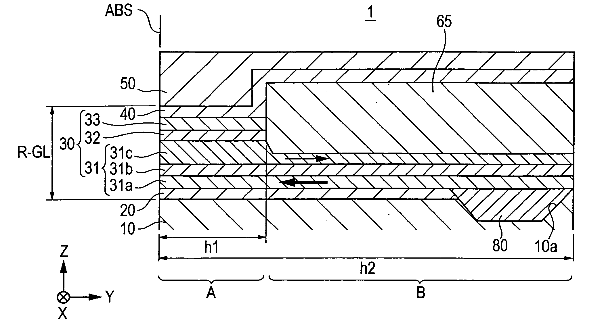
[0034] The present invention will be described based on the drawings. In the respective drawings, the x-direction is a track-width direction. The y-direction is the height direction (direction of leakage flux from a storage medium) of the GMR element. The z-direction is the direction to which the storage medium moves and the stacking direction of layers constituting the GMR element.

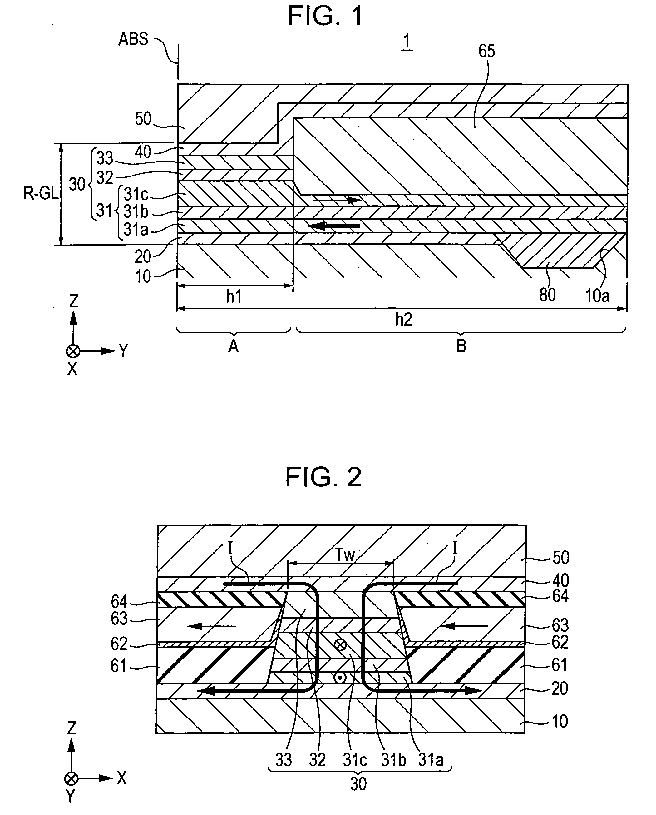
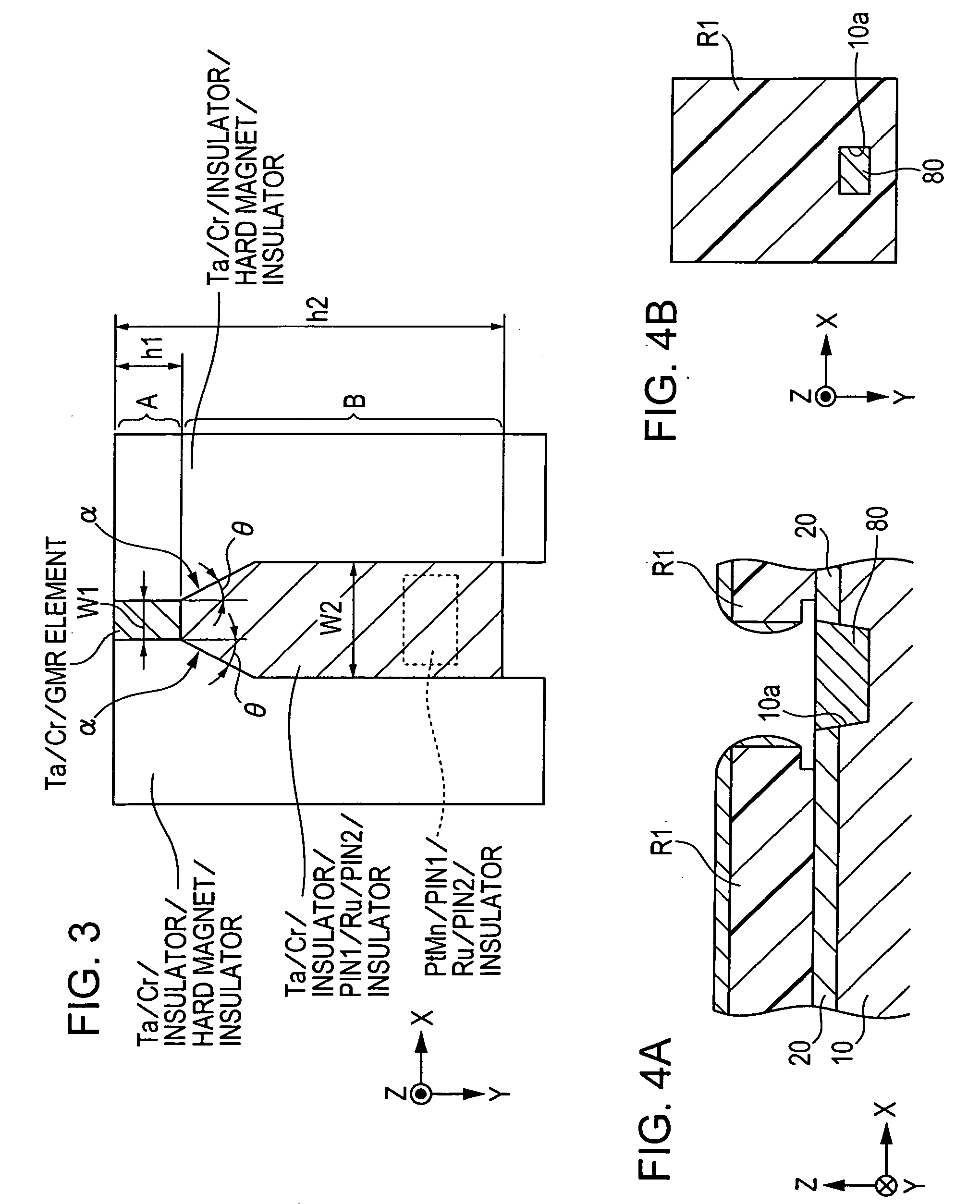
[0035] FIGS. 1 to 9B each show a first embodiment of a CPP giant magnetoresistive head (hereinafter referred to as “CPP-GMR head”) according to the present invention. FIG. 1 is a fragmentary sectional view through the center of a CPP-GMR head 1. FIG. 2 is a fragmentary plan view of the CPP-GMR head 1 when viewed from the surface facing a storage medium. FIG. 3 is a schematic plan view of a GMR element 30 when viewed from above.

[0036] The CPP-GMR head 1 includes a large-area lower nonmagnetic metal film 20, the GMR element 30 exhibiting the giant magnetoresistive effect, and a large-area upper nonmagneti...


PUM


Abstract

A CPP giant magnetoresistive head includes a lower shield layer; an upper shield layer; and a giant magnetoresistive element (GMR) between the lower shield layer and the upper shield layer. The GMR includes a nonmagnetic material layer; a pinned magnetic layer; and a free magnetic layer. The pinned layer and the free layer are laminated with the nonmagnetic layer provided therebetween. A current flows perpendicularly to a film plane of the GMR, the pinned magnetic layer extends in the height direction longer than in a track-width direction and includes a first portion in the GMR. The first portion is disposed above or below the nonmagnetic layer and the free layer. A second portion is behind the nonmagnetic layer and the free layer in the height direction. The first and second portions are in the same plane. The width of the pinned layer in the track-width direction in the first portion is greater than that in the second portion.

Description

BACKGROUND OF THE INVENTION [0001] 1. Field of the Invention [0002] The present invention relates to a CPP giant magnetoresistive head in which a sense current flows in the thickness direction (direction orthogonal to the film surface). [0003] 2. Description of the Related Art [0004] Giant magnetoresistive elements (GMR elements) used as thin-film magnetic heads can be broadly divided into a current-in-plane (CIP) mode element, in which a sense current flows in the direction parallel to a surface of a layer constituting the element; and a current-perpendicular-to-plane mode element, in which a sense current flows in the direction perpendicular to a surface of a layer constituting the element. [0005] The following description is disclosed in Japanese Unexamined Patent Application Publication Nos. 2001-266313, 2001-307307, 2002-289945, 2002-305338, and 2003-31871, and U.S. Pat. No. 5,739,987. FIG. 12 is a longitudinal sectional view showing an example of a structure of a CPP-GMR head ...

Claims


Application Information

Patent Timeline
IPC IPC(8): G11B5/127G11B5/33G11B5/39H01L43/08
CPCG11B5/39G11B5/3163G11B5/398
Inventor HAYAKAWA, YASUONISHIYAMA, YOSHIHIROAOKI, DIGOSAITO, MASAMICHIISHIBASHI, NAOHIROHONDA, KENJI
Owner TDK CORPARATION
Why Eureka
Try Eureka