Magnetic oscillator, magnetic head, and magnetic recording and reproducing apparatus

a technology of magnetic oscillator and magnetic head, which is applied in the field of magnetic oscillator, magnetic head, and magnetic recording and reproducing apparatus, can solve the problems of not only the noise component, but also the pure signal component, and the noise is large, so as to achieve the effect of suppressing magnetic white nois

Inactive Publication Date: 2006-02-23
KK TOSHIBA
View PDF4 Cites 39 Cited by
  • Summary
  • Abstract
  • Description
  • Claims
  • Application Information

AI Technical Summary

Benefits of technology

[0012] The present invention has been made in view of the above circumstances, and an object thereof is to provide a resonant magneto-resistance effect element which can suppress magnetic white noises as far as possible.

Problems solved by technology

However, there is such a problem that not only a pure signal component but also a noise component due to a shot noise become large, and an S / N ratio (a signal-noise ratio) is not improved.
Since shortage between the upper and lower electrodes becomes easier to occur according to thinning of the tunnel insulating layer, which leads to reduction of a MR ratio, it becomes exponentially difficult to manufacture an element.
The respective elements described above utilize the magneto-resistance effect in a board sense, but a problem about a magnetic white noise common to these elements emerges suddenly in recent years.
However, the artificial ferromagnetic material includes many difficult points for practical application due to necessity of a film forming technique with a high level.
Therefore, sufficient characteristics can not be obtained currently.
As described above, though development of a novel magnetic sensor utilizing a resonant magneto-resistance effect has been gone ahead in order to solve the problem about the magnetic white noise adversely affecting the high density magnetic recording, sufficient characteristics for solving the problem have not been achieved yet.

Method used


Image

  • Magnetic oscillator, magnetic head, and magnetic recording and reproducing apparatus
  • Magnetic oscillator, magnetic head, and magnetic recording and reproducing apparatus
  • Magnetic oscillator, magnetic head, and magnetic recording and reproducing apparatus

Examples


first embodiment

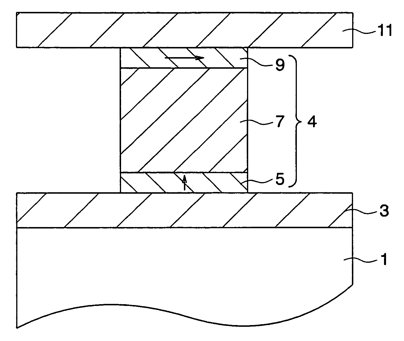
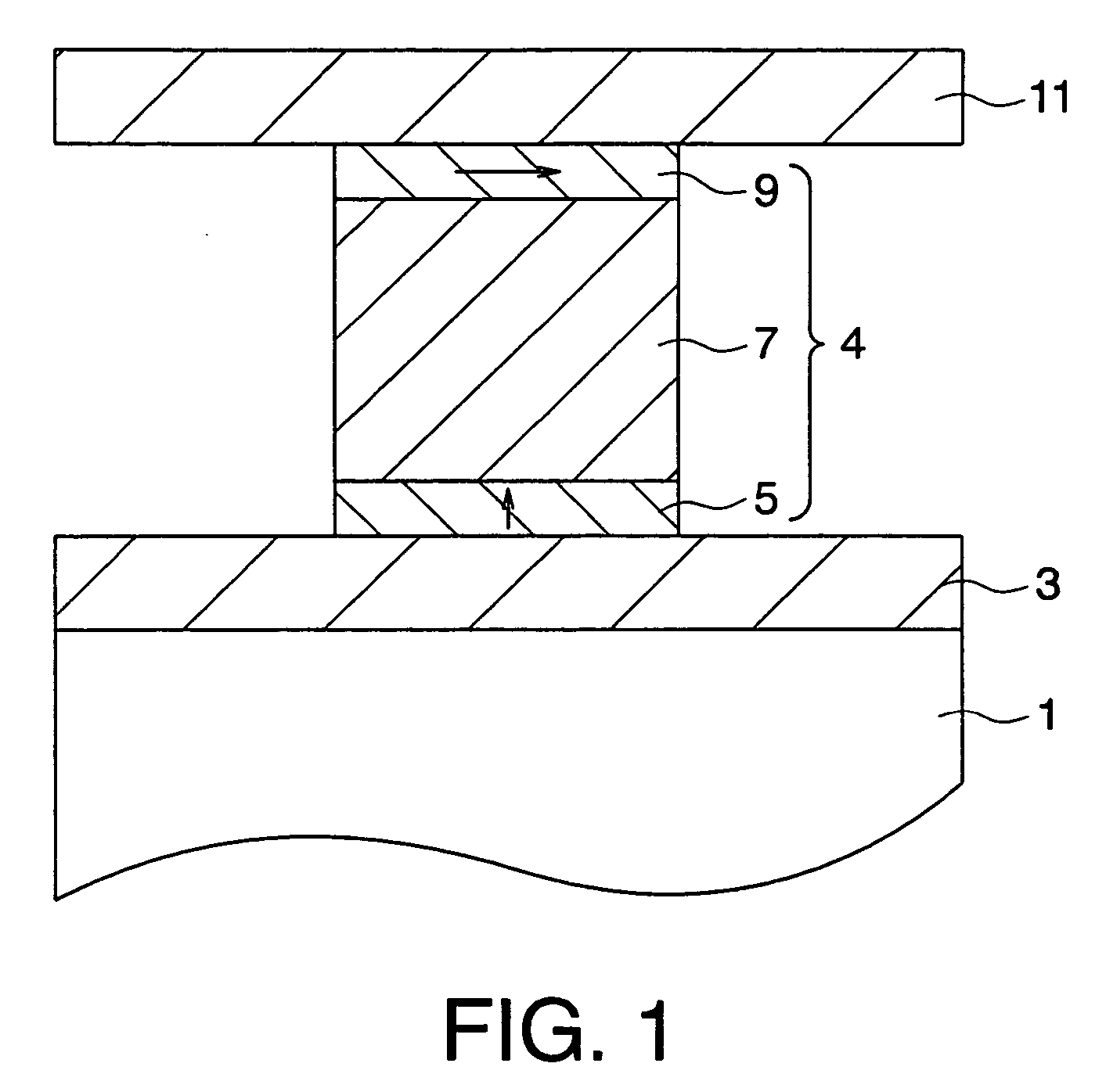
[0032] A resonant magneto-resistance effect element according to a first embodiment of the present invention is shown in FIG. 1. FIG. 1 is a sectional view showing the resonant magneto-resistance effect element according to the embodiment. The resonant magneto-resistance effect element according to the embodiment is provided on a substrate 1 with a lower electrode 3 also serving as a magnetic shield, a ferromagnetic layer 5 which is provided on the lower electrode 3 and whose magnetization direction is substantially perpendicular to a film plane, a non-magnetic layer 7 which is provided on the ferromagnetic layer 5, a ferromagnetic layer 9 which is provided on the non-magnetic layer 7 and whose magnetization direction is substantially perpendicular to the film plane, and an upper layer 11 which is provided on the ferromagnetic layer 9 and also serves as a magnetic shield. The ferromagnetic layer 5, the non-magnetic layer 7, and the ferromagnetic layer 9 have the same plan shape to c...

second embodiment

[0060] The first embodiment is directed to the resonant magneto-resistance effect element where the ferromagnetic layer 9 and the ferromagnetic layer 5 whose magnetization direction is substantially perpendicular to a film plane are each provided as a single layer, and the stacked film 4 formed via the non-magnetic layer is provided as a single piece.

[0061] A resonant magneto-resistance effect element according to the second embodiment has a plurality of the stacked films 4 according to the first embodiment which have been stacked. By stacking a plurality of the stacked films according to the first embodiment, spin fluctuation generated by the ferromagnetic layers whose magnetization directions are substantially parallel to the film planes sequentially induce resonances in the ferromagnetic layers whose magnetization directions are substantially perpendicular to the film plane, so that a further larger output voltage ΔV can be obtained. As shown in FIG. 4A, it is preferable that th...

third embodiment

[0063] Next, a resonant magneto-resistance effect element according to a third embodiment of the invention will be explained with reference to FIG. 9. A resonant magneto-resistance effect element of the embodiment has a constitution that a perpendicularly magnetizing bias film 22 is provided between the ferromagnetic layer 9 and the upper electrode 11 in the resonant magneto-resistance effect element according to the first or second embodiment.

[0064] In the first and second embodiments, change of external magnetic field applied within a plane of the ferromagnetic layer 5 is detected as change of a resonant frequency of the ferromagnetic layer 5 shown by Equation (7), but it is detected as change of a resonant frequency of the ferromagnetic layer 9 in the third embodiment. The smaller a difference between a shape anisotropy magnetic field 4πM and a crystalline anisotropy magnetic field HA perpendicular to the film plane, the larger change of a magnetic field frequency of a resonant ...


PUM

PropertyMeasurementUnit
thicknessaaaaaaaaaa
thicknessaaaaaaaaaa
angle of inclinationaaaaaaaaaa

Abstract

The present invention is to be capable of suppressing magnetic white noises as far as possible. A resonant magneto-resistance effect element includes a first magnetic layer whose magnetization direction is substantially parallel to a film plane, a second magnetic film whose magnetization direction is substantially perpendicular to the film plane, and a non-magnetic layer which is provided between the first and second layers.

Description

CROSS-REFERENCE TO RELATED APPLICATION [0001] This application is based upon and claims the benefit of priority from prior Japanese Patent Application No. 2004-237463 filed on Aug. 17, 2004 in Japan, the entire contents of which are incorporated herein by reference. BACKGROUND OF THE INVENTION [0002] 1. Field of the Invention [0003] The present invention relates to a magnetic oscillator, a magnetic head, and a magnetic recording and reproducing apparatus. [0004] 2. Related Art [0005] Since advent of a GMR (giant magneto-resistance) head utilizing a giant magneto-resistance effect (GMR effect), a recording density in magnetic recording is improved at 100% annually. The GMR element is constituted of a stacked film having a sandwich structure of a ferromagnetic layer / a non-magnetic layer / a ferromagnetic layer. The GMR element is a device utilizing a magneto-resistance effect of a so-called spin valve film, which is constituted such that magnetization of one of the ferromagnetic layers ...

Claims


Application Information

Patent Timeline
Patent Type & Authority Applications(United States)
IPC IPC(8): G11B5/33G11B5/127
CPCB82Y25/00G11B5/3903G01R33/093
Inventor SATO, RIE
Owner KK TOSHIBA
Why Eureka
Try Eureka