Signal simulation device

a signal simulation and signal technology, applied in the direction of measurement devices, instruments, antennas, etc., can solve the problems of only having relatively limited multipath propagation options for receivers, large measuring chambers, and only simulated imperfect movement of satellites

Inactive Publication Date: 2008-10-07
DEUTSCHES ZENTRUM FUER LUFT & RAUMFAHRT EV
View PDF2 Cites 30 Cited by
  • Summary
  • Abstract
  • Description
  • Claims
  • Application Information

AI Technical Summary

Benefits of technology

[0013]According to the present invention, which refers to a signal simulation device of the type initially mentioned, this object is achieved in an advantageous manner by configuring the digital matrix processor, which is combined and synchronized with the signal processor, such that by a complex weighting of its input signals from the signal generator, the amplitude and phase shift are simulated that depend on the direction of incidence of the signals and the position of the antenna array element of the receiver that is associated to the output, the weighting coefficients being calculated externally on a control computer and inputted into the matrix processor via an interface, and that for generating additional multipath signals within the digital matrix processor, means are provided to additionally convolute the input signals with the impulse response of a multipath channel, the coefficients of the impulse response being calculated using a vector channel model.

Problems solved by technology

One of the main sources of interferences in satellite navigation are multipath signals, i.e. signals that impinge on the antenna of the navigation receiver only after having been reflected once or several times, e.g. by buildings.
However, these receivers only have relatively limited possibilities to factor multipath propagation in; the output signals include no information on directions.
A simulation using distributed antennas in an anechoic measuring chamber is disadvantageous in that, on the one hand, a rather large measuring chamber is required for far field measuring, which may have dimensions of several meters in all directions, and that, on the other hand, the movement of a satellite can only be simulated imperfectly.
The disadvantage of an analog device for generating the plane wavefronts consists in the high hardware effort for the realization, which increases proportional to the product of the input and output signals.
Compared to a digital solution, the analog variant is much less versatile, since modifications always require a new hardware design.
An additional multipath channel simulation within this analog unit is not possible.

Method used


Image

  • Signal simulation device
  • Signal simulation device
  • Signal simulation device

Examples


Embodiment Construction

[0022]Referring to FIG. 1 and FIG. 2, the generation of a wave front performed with a satellite signal simulation device of the present invention will now be described.

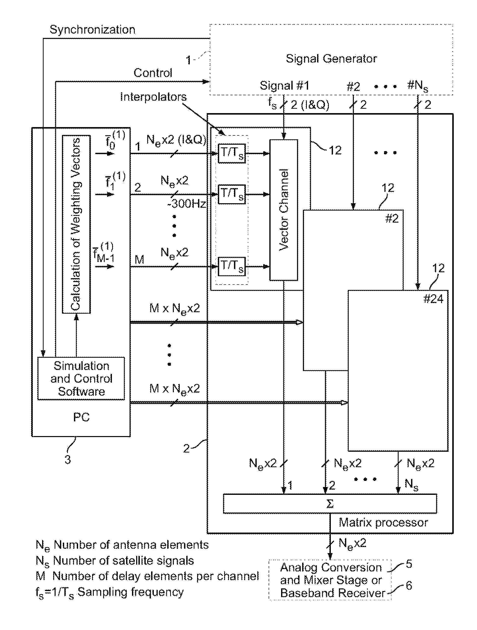
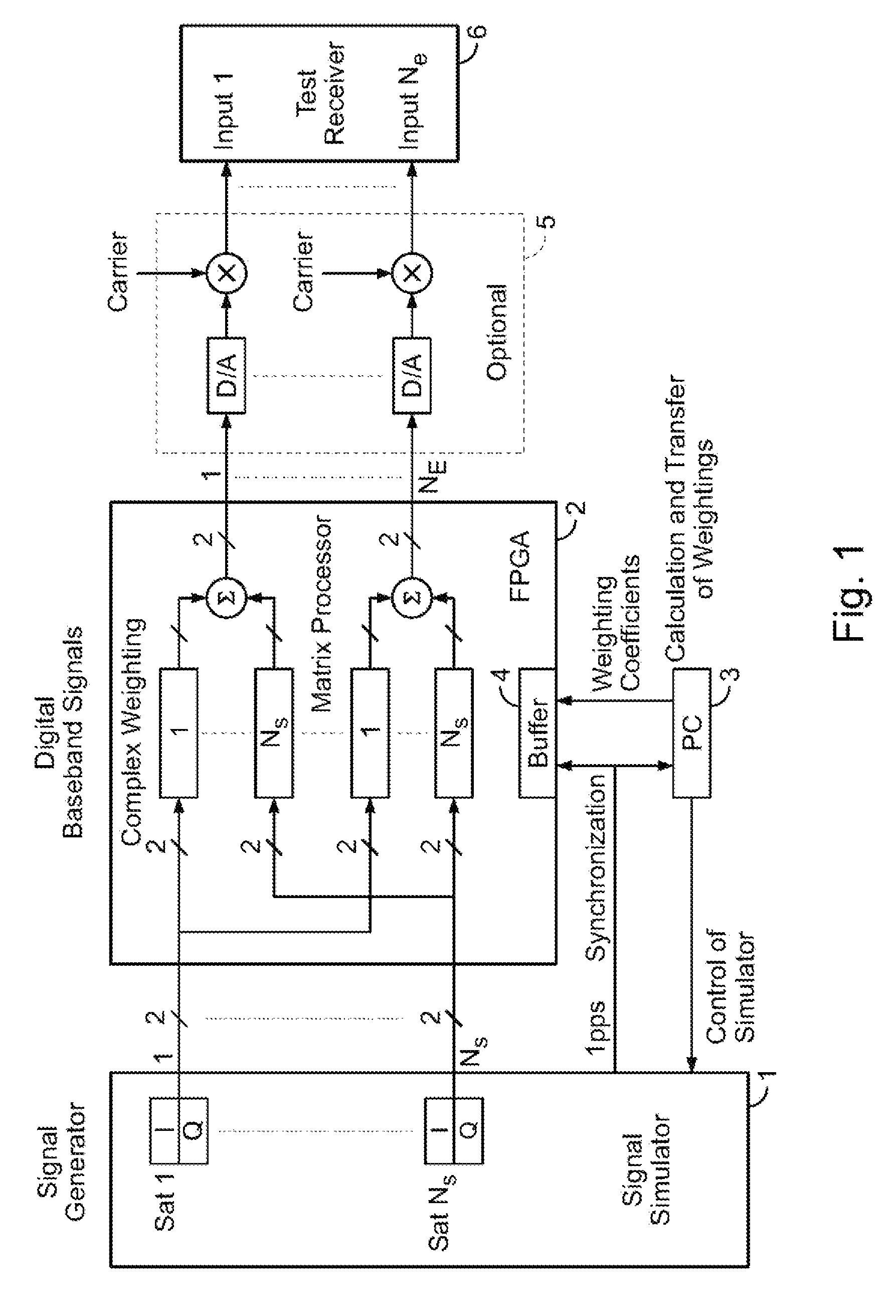
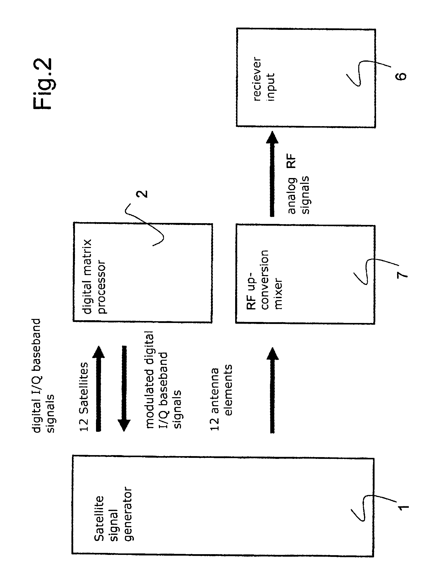
[0023]Separated by in-phase channel and quadrature channel Q, the digitalized complex baseband signals (1, . . . , Ns) of a plurality of satellites Sat 1 to Sat Ns, generated reproducibly by a signal generator 1, are each fed into digital matrix processor 2 configured from one or more FPGA (Field Programmable Gate Arrays), where they are complexly multiplied by different weighting factors, which, given an adequate choice of weighting factors, corresponds to an adjustment of the amplitude and a shifting of the carrier phase. Thereafter, the signals are combined, i.e. added, and delivered at outputs as digital signals, again split up into in-phase and quadrature components I and Q, respectively.

[0024]The matrix processor 2 has a plurality of such outputs, namely one for each antenna array element of a test receiver 6 to...


PUM


Abstract

A signal simulation device for testing and developing radio receivers adapted to orientate antenna beams to different radio transmitters and to simultaneously suppress interference signals, comprises an antenna array, a signal generator generating reproducible digital signals in the complex baseband, and a digital matrix processor combined and synchronized with the signal generator. The processor has input signals generated by the signal generator and has output signals that form received signals of the antenna array. The input signals of the matrix processor are phase shifted according to a direction of incidence and to relative positions of the elements within the antenna array of the radio receiver, and are combined and supplied to outputs of the matrix processor. Amplitude and phase shift are simulated by weighting of the input signals from the signal generator, the weighting coefficients being calculated on a control computer and input into the matrix processor via an interface.

Description

TECHNICAL FIELD OF THE INVENTION[0001]The present invention is directed to a signal simulation device for testing and developing radio receivers, in particular satellite navigation receivers, which are adapted to orientate a plurality of independent antenna beams to different signal-emitting radio transmitters and to simultaneously suppress interference signals and which further comprise an adaptively controllable antenna array composed of elements, using a signal generator generating a plurality of reproducible digital signals in the complex baseband and a digital matrix processor combined and synchronized therewith, whose input signals are the digital signals generated by the signal generator in the complex baseband and whose output signals form the received signals of the individual elements of the antenna array of the radio receiver, the input signals of the matrix processor being modulated in the digital portion within this matrix processor by phase shifting according to their ...

Claims


Application Information

Patent Timeline
Patent Type & Authority Patents(United States)
IPC IPC(8): H01Q3/00G01S1/02G01S19/23
CPCG01S1/028G01S19/23
Inventor HORNBOSTEL, ACHIMSCHROTH, ARNOKONOVALTSEV, ANDRIYSTEINGASS, ALEXANDERECKARDT, ANDREASVENUS, HOLGER
Owner DEUTSCHES ZENTRUM FUER LUFT & RAUMFAHRT EV
Why Eureka
Try Eureka