
Hydraulic vehicle brake

a technology for vehicle brakes and brakes, applied in the direction of brake cylinders, fluid actuated brakes, anti-theft devices, etc., can solve the problems of increased material and manufacturing costs, increased structural effort, and additional structural risk of vehicle manufacturers, and achieves the effect of simple and low-cos

Inactive Publication Date: 2008-10-14
CONTINENTAL TEVES AG & CO OHG
View PDF23 Cites 34 Cited by
  • Summary
  • Abstract
  • Description
  • Claims
  • Application Information

AI Technical Summary

Benefits of technology

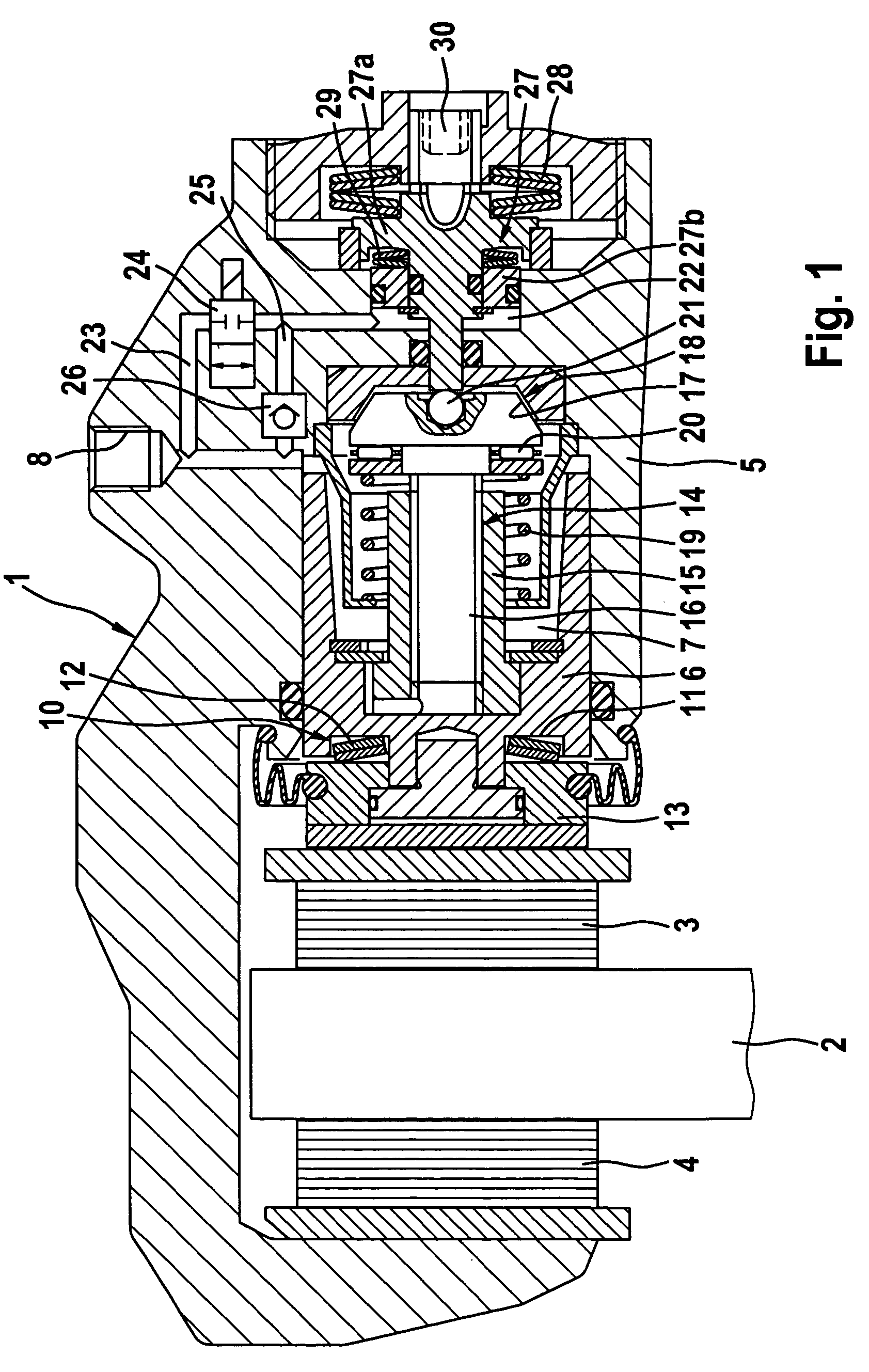
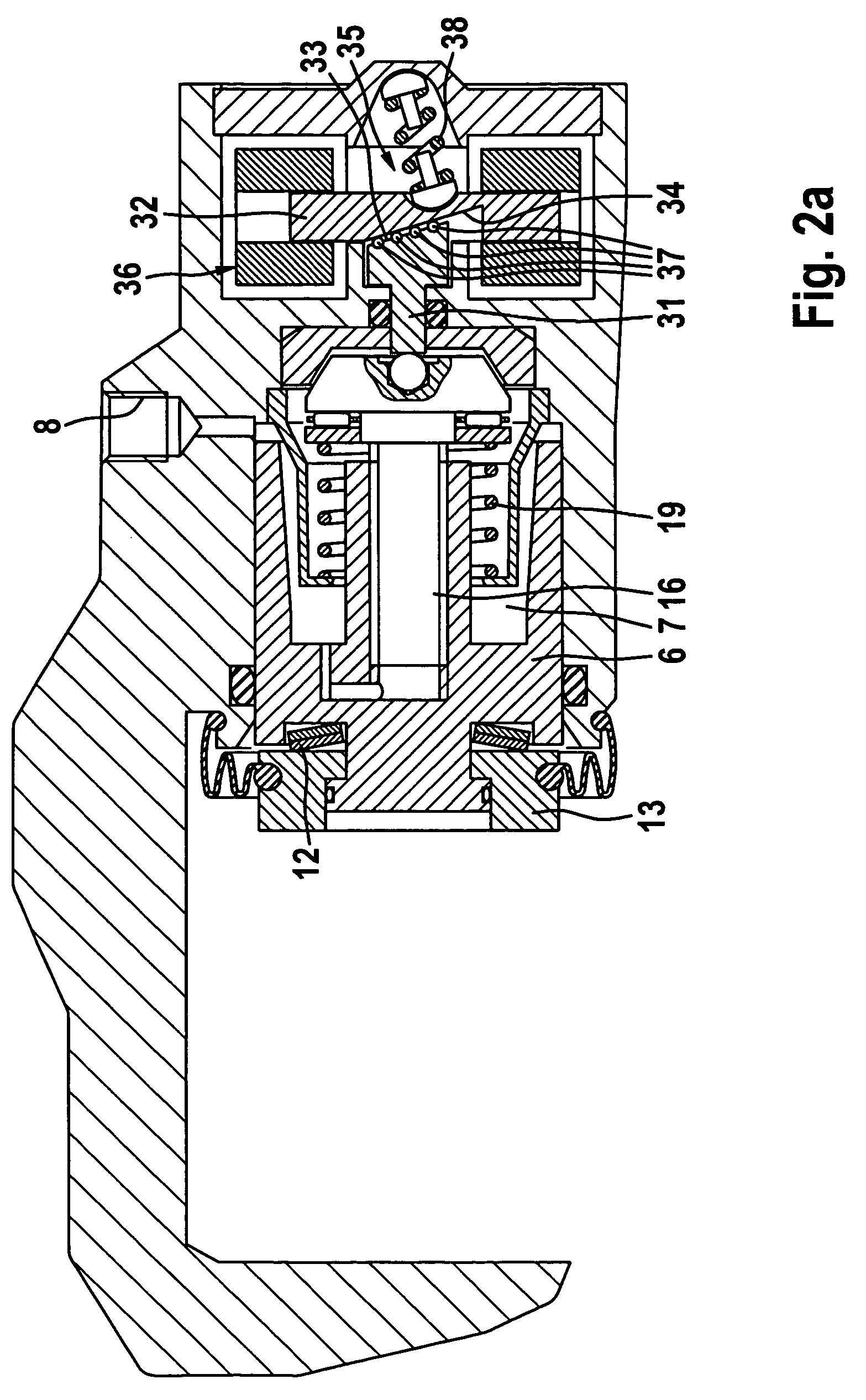
[0006]In view of the above, an object of the invention is to improve a hydraulic vehicle brake with a parking brake device of the type mentioned hereinabove to such effect that the parking brake function is realized in a simple and low-cost manner, while legal requirements are complied with.

Problems solved by technology

However, these assemblies suffer from the shortcoming that an additional brake cable must be provided apart from the hydraulic supply line for each brake.
The result is an increased expenditure in material and manufacture.
Beside the disadvantage incurred by an increase assembly effort, the vehicle manufacturer must additionally bear the risk of a faulty assembly.
An electromotive adjusting apparatus of this type, which acts directly on the position of the brake pedal, admittedly, relieves the driver in terms of the force effort to be made in a parking brake operation, yet entails additional structural effort.
The result is that additional costs are incurred.

Method used


Image

  • Hydraulic vehicle brake
  • Hydraulic vehicle brake
  • Hydraulic vehicle brake

Examples


fourth embodiment

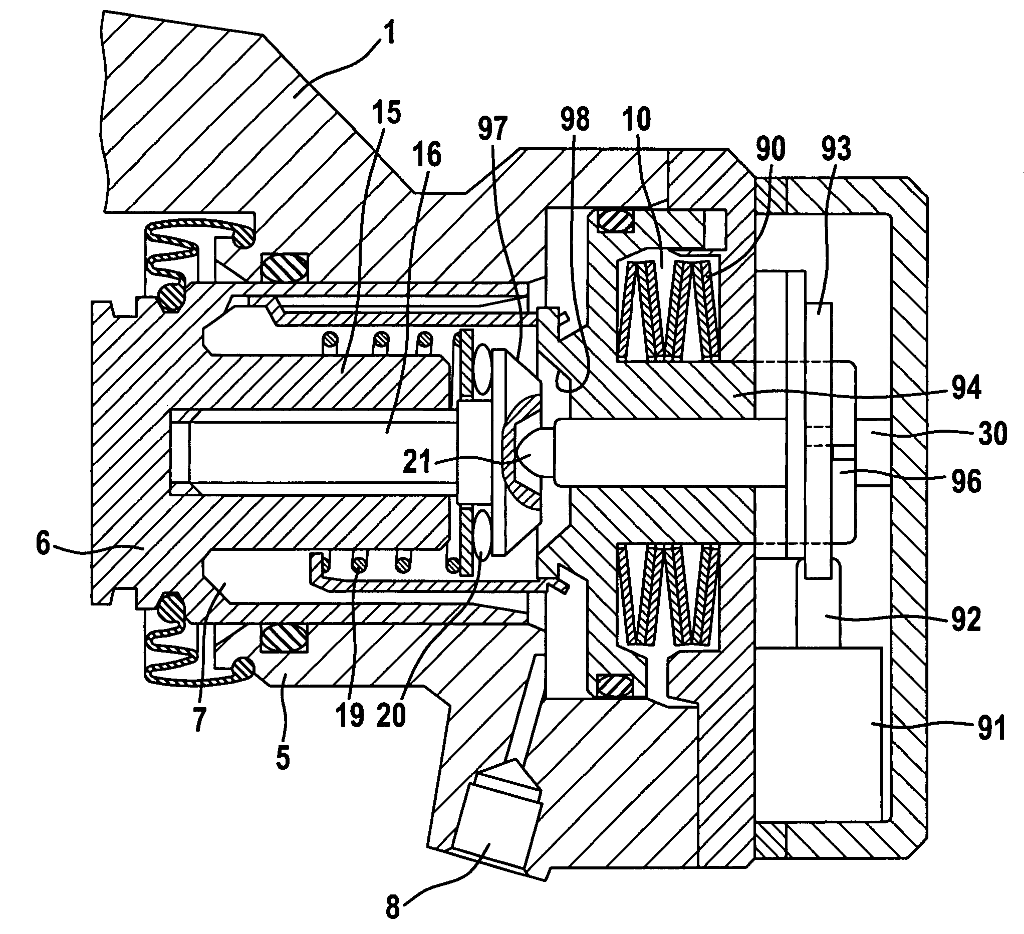
[0049]The arrangement of the energy accumulator 10 in the subject matter of the invention illustrated in FIG. 4 corresponds to the third design according to FIGS. 3a, b. In this design the service pressure chamber 7 is additionally used as an accumulator pressure chamber, which is delimited by an accumulator piston 54 on the right-hand side in the drawing. The above-mentioned spring element is formed of a spring assembly 60 being supported on the accumulator piston 54. The locking device is again configured as a threaded-nut / spindle assembly, having its spindle 56 rigidly connected to the brake piston 6. A threaded nut 55 coupled with the spindle 56 by way of a non-self-locking thread includes a first friction surface 57, which cooperates with or is moved into engagement with a second friction surface 58 when the parking brake device is locked. In this arrangement, the second friction surface 58 is preferably designed at the end of an axial extension 59 of the accumulator piston 54,...

fifth embodiment

[0050]Likewise the invention illustrated in FIG. 5 has a similar design of the locking device. The accumulator piston 64 is additionally used as a radial guide of the spindle 66 of the threaded-nut / spindle assembly, with a cardan-type joint 67 being designed at the end of the spindle 66. Said joint 67 cooperates with a toothed wheel 68 of an angular gear 70 that is used to transmit the rotation of the output shaft of an electric motor 69 onto the spindle 66. A threaded nut 65 coupled to the spindle 66 by means of a self-locking thread includes a first contact surface 71, which cooperates with or is moved into engagement with a second contact surface 72 when the parking brake device is locked. Said second contact surface 72 is preferably designed in the brake piston 6.

[0051]When the parking brake is applied, hydraulic pressure is built up in the service pressure chamber 7, exactly as in the design according to FIG. 4, said pressure causing displacement of the brake piston 6 to the le...


PUM


Abstract

A hydraulic vehicle brake equipped with a parking brake device, in particular for motor vehicles, including a brake housing in which a hydraulic service pressure chamber is delimited by a brake piston, wherein the parking brake device acts on the brake piston and, in the applied condition, can be locked by a locking device, and an energy accumulator cooperating with the brake piston is equipped with at least one integrated spring element. In order to realize a simple and low-cost parking brake function that complies with legal requirements, according to the invention, the parking brake device is operable by a pressure that is introduced into the service pressure chamber and enables charging the energy accumulator.

Description

TECHNICAL FIELD[0001]The present invention generally relates to hydraulic vehicle brakes equipped with parking brake devices and more particularly relates to a hydraulic vehicle brake equipped with a parking brake device, in particular for motor vehicles, including a brake housing in which a hydraulic service pressure chamber is delimited by a brake piston, wherein the parking brake device acts on the brake piston.BACKGROUND OF THE INVENTION[0002]DE 197 11 382 C2 discloses a hydraulic vehicle brake of this type.[0003]In the prior art brake, the brake is applied in the parking brake mode by means of a two-stage gear driven by an electric motor. A parking brake operation is effected by way of energizing the electric motor, while the spring element of the energy accumulator is preloaded in addition. A reversed rotation of the electric motor is necessary for the release operation of the parking brake.[0004]Also, combined service and parking brakes are known in the art, wherein there is ...

Claims


Application Information

Patent Timeline
Patent Type & Authority Patents(United States)
IPC IPC(8): B60T13/04F16D65/14F16D65/18
CPCF16D65/18F16D2066/003F16D2121/02F16D2123/00F16D2125/40F16D2125/48F16D2125/52F16D2125/582F16D2127/04F16D2127/06F16D2129/02F16D2129/08F16D2129/10F16D65/14
Inventor HALASY-WIMMER, GEORGSCHIEL, LOTHARWEILER, ROLFBALZ, JURGENSCHACK, PETERBAUER, THOMASDRUMM, STEFAN A.HEISE, ANDREASSCHOLER, JOACHIMSCHMITT, STEFAN JOHANNESPOHLMANN, ANDREASWINKLER, THOMASKNOP, VOLKERSCHRIEFER, JORNHARTMANN, RALFSCHILLE, KARSTENGORLACH, JOHANNESVOLZ, PETER
Owner CONTINENTAL TEVES AG & CO OHG
Learn More