
Method and device for operating an internal combustion engine having exhaust-gas recirculation

a technology of internal combustion engine and exhaust gas, which is applied in the direction of electrical control, process and machine control, instruments, etc., can solve the problems of complex coordination between, unsatisfactory torque change, and additional pollution from emissions, and achieve the effect of simple and low-cos

Inactive Publication Date: 2007-05-29
ROBERT BOSCH GMBH
View PDF7 Cites 31 Cited by
  • Summary
  • Abstract
  • Description
  • Claims
  • Application Information

AI Technical Summary

Benefits of technology

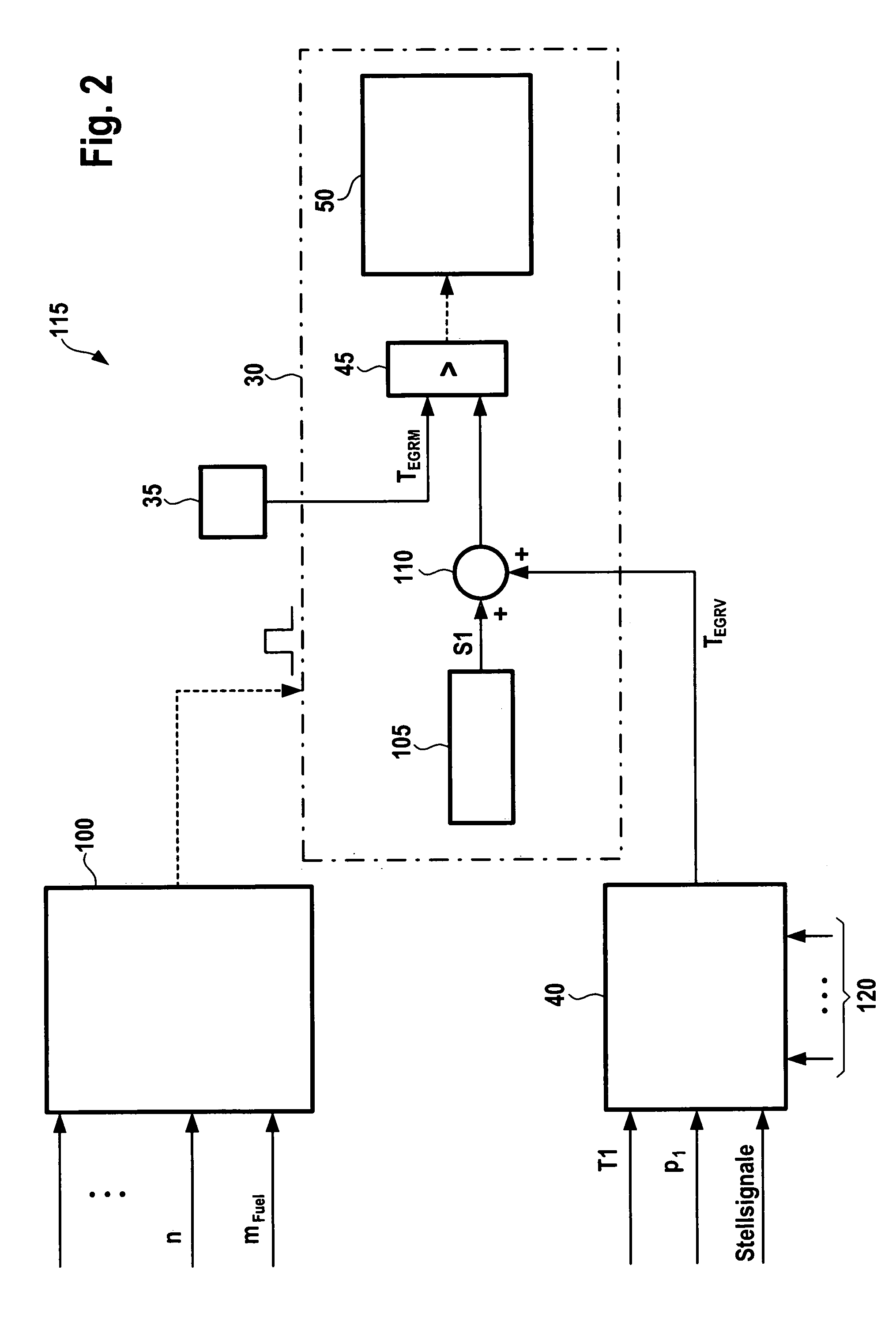
The present invention provides a method and device for monitoring the functioning of a cooling device in an internal combustion engine with exhaust-gas recirculation. The invention uses measured values to determine the variable characteristic of the cooling device functioning, and compares it to a specified value to detect any deviation. The deviation is considered an error if it exceeds a predefined threshold value. The monitoring is simple and low-cost, and it can be carried out during normal operation of the engine. The invention also suggests selecting specific operating points for monitoring, such as mass flow rate of recirculated exhaust gas or engine operating points at steady-state. The monitoring results can help prevent malfunctions of the cooling device and allow for early indication of potential malfunctions. The use of efficiency of the cooling device or temperature downstream from the cooling device as a variable characteristic of the cooling device functioning is also recommended.

Problems solved by technology

In this context, it is problematic that extreme control actions of the exhaust-gas recirculation valve can lead to undesired torque changes and additional pollution from emissions.
Since the inertia of the temperature sensors causes the action to last relatively long, during this time complex coordination is necessary between other operating modes, such as NOx-catalyst regeneration, etc., which also act on the exhaust-gas recirculation valve.

Method used


Image

  • Method and device for operating an internal combustion engine having exhaust-gas recirculation
  • Method and device for operating an internal combustion engine having exhaust-gas recirculation
  • Method and device for operating an internal combustion engine having exhaust-gas recirculation

Examples


Embodiment Construction

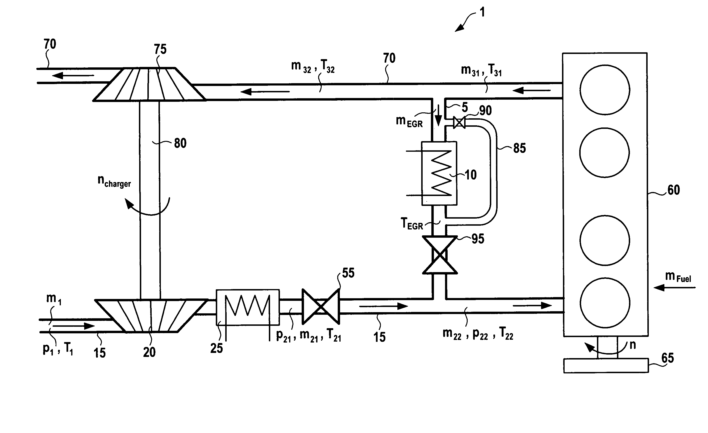
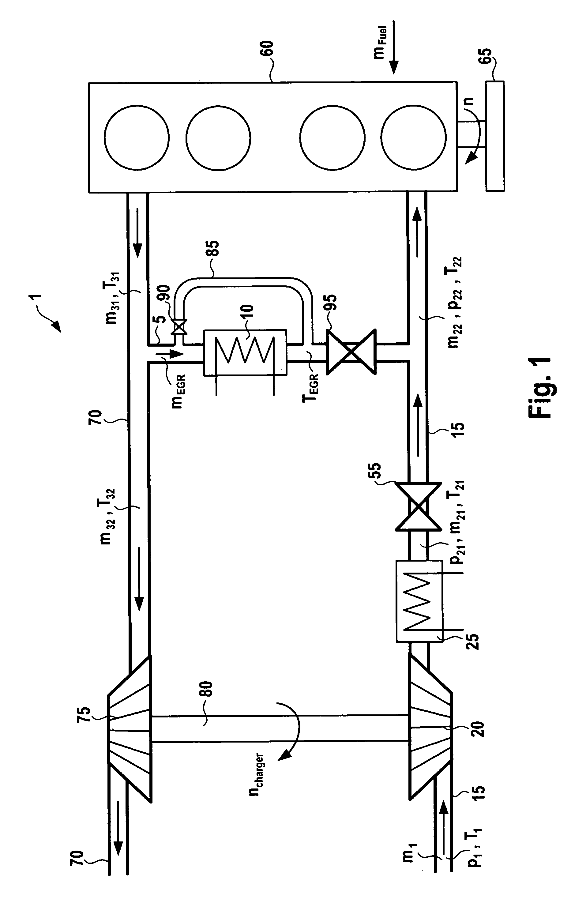
[0013]In FIG. 1, reference numeral 1 designates an internal combustion engine, which propels a vehicle, for example. Internal combustion engine 1 may be, for example, a spark-ignition engine or a diesel engine. In the following, it is exemplarily assumed that internal combustion engine 1 is a diesel engine. It includes a cylinder block 60, which is supplied fresh air via an air supply 15. The flow direction of the fresh air in air supply 15 is indicated in FIG. 1 by arrows. In air supply 15, the fresh air supplied to cylinder block 60 is compressed by a compressor 20. An intercooler 25, which re-cools the fresh air compressed and heated by the compressor, is situated in air supply 15, downstream from compressor 20 in the direction of flow. A throttle valve 55 is situated in air supply 15, downstream from intercooler 25 in the flow direction of the fresh air. An exhaust-gas recirculation line 5 of internal combustion engine 1 opens out into air supply 15, downstream from throttle val...


PUM


Abstract

Provided are a method and device for operating an internal combustion engine having exhaust-gas recirculation, the method and device allowing a diagnosis of an exhaust-gas recirculation cooler during normal operation of the internal combustion engine. In this context, a variable characteristic of the functioning of the exhaust-gas recirculation cooler is monitored. The variable characteristic of the functioning of the cooling device is ascertained as a function of a measured value. The variable characteristic of the functioning of the exhaust-gas recirculation cooler is specified on the basis of an intact exhaust-gas recirculation cooler. The ascertained value of the variable characteristic of the functioning of the exhaust-gas recirculation cooler is compared to the predefined value. An error is detected when the ascertained value of the variable characteristic of the function of cooling device deviates from the specified value.

Description

FIELD OF THE INVENTION [0001]The present invention relates to a method and a device for operating an internal combustion engine having exhaust-gas recirculation.BACKGROUND INFORMATION [0002]Methods and devices for operating an internal combustion engine having exhaust-gas recirculation are well-known. In this context, it is also known that a cooling device can be provided in an exhaust-gas recirculation line for cooling the recirculated exhaust gas. Since the cooling device in the exhaust-gas recirculation line has an effect on the exhaust-gas emissions of the internal combustion engine, the legislature requires, in the case in which the internal combustion engine drives a vehicle, that the cooling function of the cooling device be monitored within the scope of an on-board diagnosis. Above all, the monitoring is necessary in order that the American OBDII limit values for exhaust-gas emissions can be satisfied.[0003]German Patent No. 100 03 060 describes a monitoring function, which ...

Claims


Application Information

Patent Timeline
Patent Type & Authority Patents(United States)
IPC IPC(8): F02M25/07F02B33/44F02B47/08G06F19/00
CPCF02B29/0437F02M25/0702F02M25/0728F02M25/0738F02M25/0754F02D41/0065F02D41/22F02D2041/0067F02M25/0707Y02T10/121Y02T10/146F02M26/05F02M26/49F02M26/25F02M26/33F02M26/47Y02T10/12
Inventor BUCK, RAINERFOERSTNER, DIRKBLUMENDELLER, WILHELM
Owner ROBERT BOSCH GMBH
Learn More