
Liquid dispensing apparatus using a passive liquid metering method

a liquid metering and liquid technology, applied in the direction of movable spraying apparatus, insect catchers and killers, disinfection, etc., can solve the problems of less precise and workable devices, limited liquid metering range, and environmental concerns of volatile emissions of pressurized devices, so as to achieve less sensitive to liquid properties, simple and low-cost, the effect of passiv

Active Publication Date: 2009-12-17
DAVID JEREMIAH J
View PDF99 Cites 27 Cited by
  • Summary
  • Abstract
  • Description
  • Claims
  • Application Information

AI Technical Summary

Benefits of technology

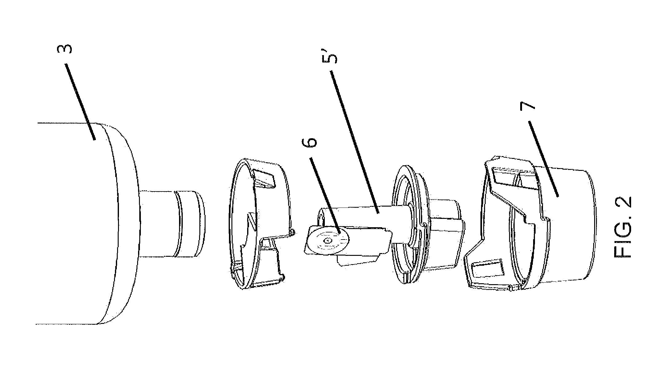
[0009]One embodiment of the present invention features an atomizing head consisting of several plates forming a small chamber of liquid. A vibrating plate that is actuated by a piezoelectric device attached to the vibrating plate compresses the chamber. The pressurized liquid is atomized as it is dispensed through a perforated membrane on the first planar member. The advantage of this design is that the device is less sensitive to the liquid properties because it directly compresses liquid in the chamber. This is an advantage compared to devices that directly vibrate the perforated membrane plate, which are more sensitive because they rely on liquid inertia to propel the liquid and therefore depend on the liquid properties, especially including viscosity and specific gravity.
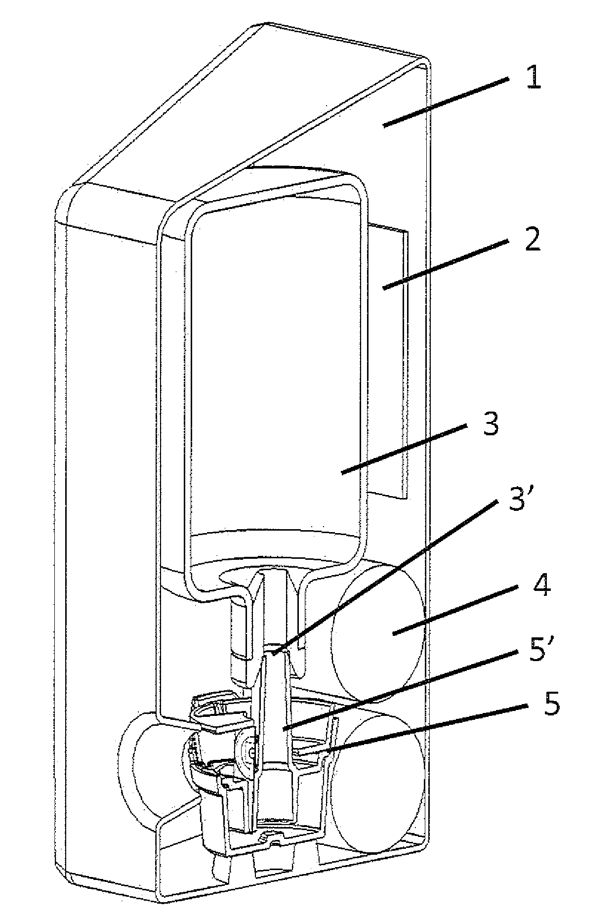
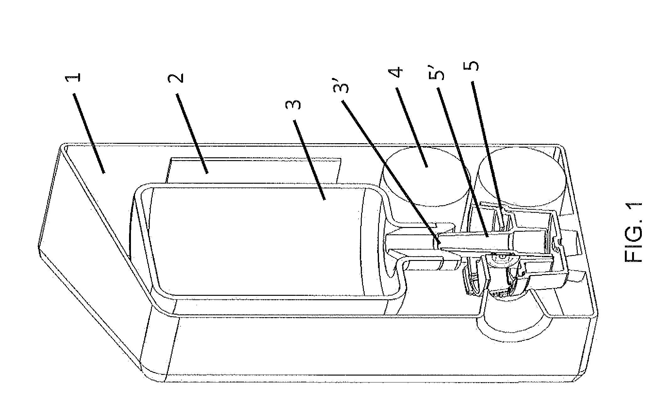
[0010]One embodiment of the present invention incorporates a new method for delivering liquid to the atomizer head. The device consists of a large liquid reservoir with a downward-pointing tube. The tube allows liquid to fall into a small liquid reservoir. An air lock between the liquid level in the small reservoir and the tube automatically maintains the desired liquid height in the small reservoir and the tube automatically maintains the desired liquid height in the small reservoir. Surface tension forces draw the liquid from the small reservoir automatically to the atomizer head with a controlled backpressure. This system provides passive metering of liquid to the atomizing head and is passive, simple and low-cost. Another advantage of this design is that there is no restriction on the size of the large reservoir.
[0011]This embodiment of the present invention requires no pressurized gas propellant (VOC's), which are increasingly regulated by both State and Federal Agencies, thereby eliminating environmental challenges associated with such aerosol devices.

Problems solved by technology

Pressurized devices have environmental concerns related to volatile emissions and are also limited by precision metering of liquids, cost and power consumption.
Some devices, such as used in a humidifier, are less precise and work only with certain types of liquids.
The wick limits the range of liquids to be used in these devices because of clogging of the wick and limitations of the viscosity of the liquid.
The vertical orientation of a wick further restricts the design because it requires that the orientation of the vibrating membrane be horizontal.
Further, the vibrating membrane in such devices is sensitive to residual accumulation of liquid on the plate.
This reduces the range of liquids that can be used in such a device.
Finally, the reservoir size that can be used in such a device is relatively small, because its height is limited by the height that a wick can draw liquid to the vibrating membrane.
These designs are appropriate for Inkjet printing but are relatively expensive because they require precise semiconductor fabrication processes.
In such designs, the delivery of liquid to the perforated membrane is a challenge and only small volume reservoirs can be used.

Method used


Image

  • Liquid dispensing apparatus using a passive liquid metering method
  • Liquid dispensing apparatus using a passive liquid metering method
  • Liquid dispensing apparatus using a passive liquid metering method

Examples


Embodiment Construction

[0019]For purposes of the description hereinafter, the words “upper”, “lower”, “right”, “left”, “vertical”, “horizontal”, “top”, “bottom”, “lateral”, “longitudinal”, “small”, “large” and like spatial terms, if used, shall relate to the described embodiments as oriented in the figures. Flowever, it is to be understood that many alternative variations and embodiments may be assumed except where expressly specified to the contrary. It is also to be understood that the specific devices and embodiments illustrated in the accompanying drawings and described herein are simply exemplary embodiments of the invention.

[0020]While specific embodiments of the invention have been described in detail, it will be appreciated by those skilled in the art that various modifications and alternatives to those details could be developed in light of the overall teachings of the disclosure. The presently preferred embodiments described herein are meant to be illustrative only and not limiting as to the sco...


PUM


Abstract

A liquid dispensing device using a piezoelectric member in connection with an atomizing head and a passive metering method to supply liquid to the atomizing head. Preferably, the device is used to but not limited to dispensing of fragrances, insecticides or other aromatic solutions. The piezoelectric member does not vibrate the nozzle plate through which the liquid is dispensed. The passive metering method relies only on surface tension forces within the supply passageway. The device can work with a wider range of liquid properties than existing piezoelectric devices of this type. The passive metering method is robust and consistent, enabling larger and more varied liquid reservoirs because the reservoir height is not a factor in determining the performance of the device. The atomizing head functions with a wider range of liquids than atomizers whose nozzle plates are directly excited.

Description

CROSS-REFERENCE AND INCORPORATION BY REFERENCE[0001]This patent application claims the benefit of domestic priority of U.S. Provisional Application Ser. No. 61 / 073,275, filed Jun. 17, 2008, and entitled “Liquid Dispensing Apparatus Using A Passive Liquid Metering Method”. U.S. Provisional Application Ser. No. 61 / 073,275 is hereby incorporated by reference in its entirety.FIELD OF THE INVENTION[0002]The subject invention relates generally to liquid dispensing devices and, more particularly, to liquid dispensing devices using piezoelectric actuation and passive metering methods.BACKGROUND OF THE INVENTION[0003]Devices exist to atomize and dispense liquids. These include liquid dispensers, medical devices, printing devices and many more. Pressurized aerosol canisters and hand-operated sprayers are the most common devices in use. Pressurized devices have environmental concerns related to volatile emissions and are also limited by precision metering of liquids, cost and power consumption...

Claims


Application Information

Patent Timeline
Patent Type & Authority Applications(United States)
IPC IPC(8): B05B17/04B05B3/14B05B9/03B05B17/06B05B12/02
CPCA01M1/205A61L9/14B05B17/0676B05B17/0638A61L2209/132B05B17/0646
Inventor LOVERICH, JACOBFRANK, JEREMY
Owner DAVID JEREMIAH J
Learn More