
Mobile joint suitable for a sitting device

a mobile joint and sitting device technology, applied in the direction of movable seats, rocking chairs, chairs, etc., can solve the problems of difficult integration in furniture, large force to be absorbed, complex mechanisms in these chairs to tilt the chair seat, etc., and achieve good resistance to exhaustion, good functionality, and small

Inactive Publication Date: 2008-10-14
VARIER FURNITURE AS
View PDF21 Cites 17 Cited by
  • Summary
  • Abstract
  • Description
  • Claims
  • Application Information

AI Technical Summary

Benefits of technology

The joint provides effective stiffness and resistance with minimal spring travel, is comfortable, and can be easily repaired or adapted, while maintaining a simple and aesthetically pleasing design, suitable for various chair constructions and applications.

Problems solved by technology

The joint is therefore highly visible, difficult to integrate in furniture, such as a chair, and produces a large spring travel.
The mechanisms in these chairs to tilt the chair seat are also complex and sometimes visible on the furniture.
The problem encountered with this solution is that relatively large forces must be absorbed by the padding material without deformation; hence the material must be relatively compact to provide sufficient resistance.
Padding of this kind is not particularly comfortable and it has proven difficult to provide a padding which also has sufficient strength.
To obtain sufficient strength, an alternative solution has been to compensate with additional padding, but this results in a bulkier piece of furniture and affects the appearance of the furniture.
However, this solution provides a very limited and imprecise tilting and also allows an unfavourable rotation in the horizontal plane of the joint elements in relation to each other.
The padding is subjected to aging and wear, especially when under tension, which changes the elastic properties of the padding.
With time, the joint will end up resting on the main bolt connecting the two joint elements and subjecting it to damageable wear, if not regularly tightened.
The disadvantage of current solutions is that the joints are complex and heavy devices which are not easily adapted to chairs where a simple design, light weight and for example the possibility to stack the chairs, is desired.

Method used


Image

  • Mobile joint suitable for a sitting device
  • Mobile joint suitable for a sitting device
  • Mobile joint suitable for a sitting device

Examples


example embodiment

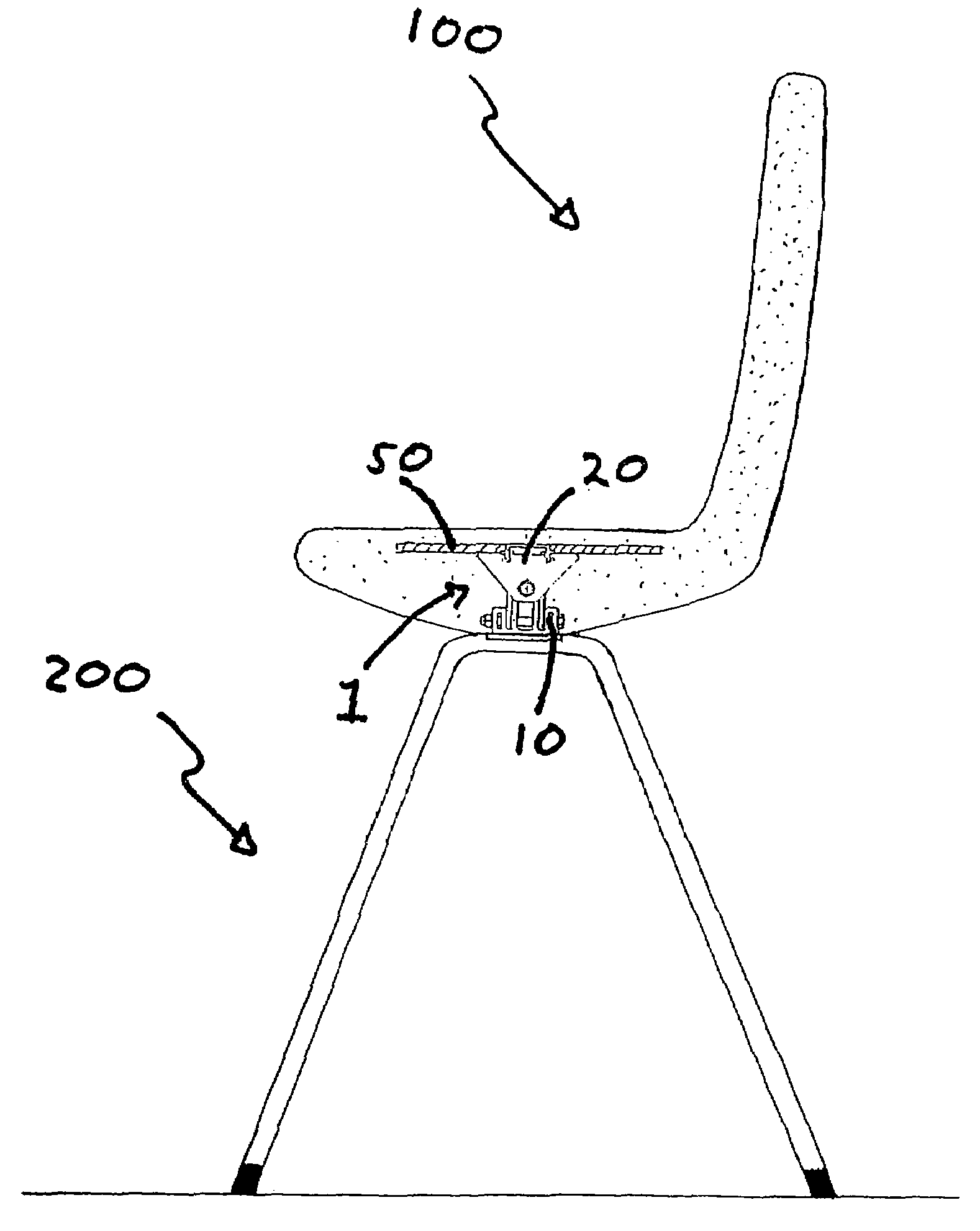
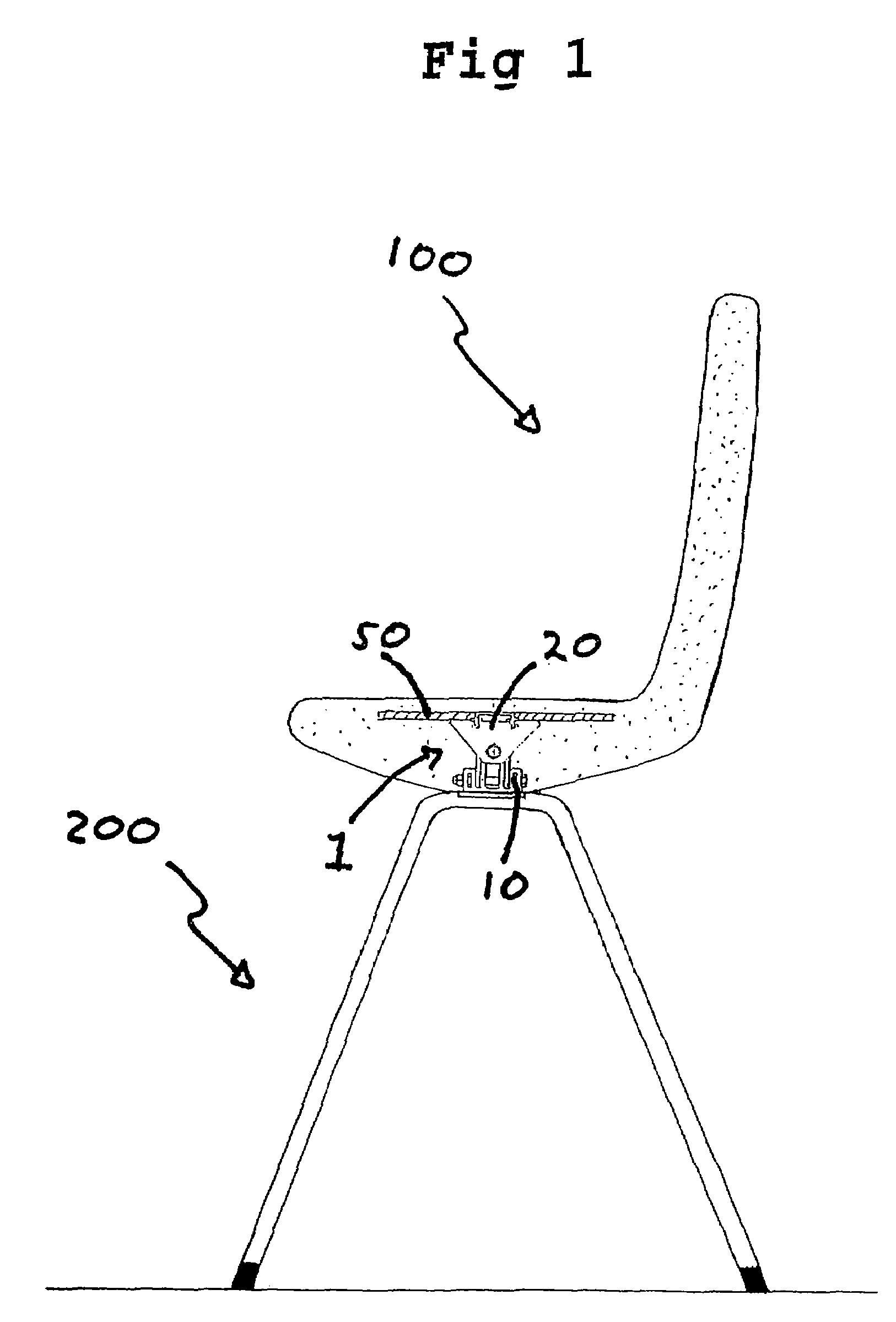
[0024]As shown in FIG. 1, the joint 1 according to the invention, is suitable as a connecting joint between a chair seat and an underframe 200. The underframe 200 comprises four legs joined in an upper mounting suitable to attach the seat of the chair.

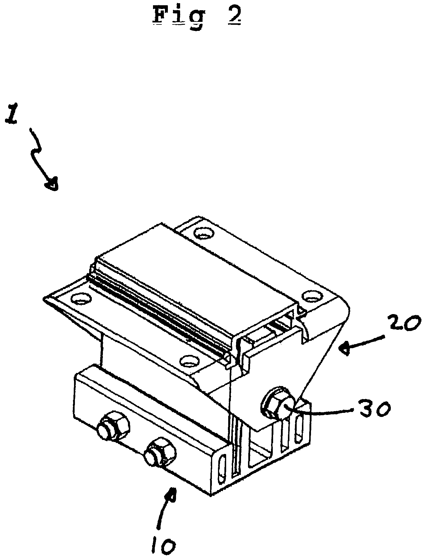
[0025]In this embodiment, the joint 1 is designed as shown in FIG. 2, comprising two joint elements, one lower joint element 10 and one upper joint element 20 which are jointed via a horizontal shaft 30. The upper joint element 20 can be tilted between two extreme positions in relation to the lower joint element 10 which it is connected to.

[0026]The lower joint element 10 in this embodiment is substantially parallel to the surface. The lower joint element 10 will be arranged to an underframe 200.

[0027]The upper joint element 20 will be arranged to the seat of the chair, and is substantially parallel to the seat of the chair. A frame 50 is moulded within the padding of the chair and constitutes the means of attachment of the seat 100 to...


PUM


Abstract

The present invention relates to a mobile joint (1) with spring resistance, suitable for a sitting device, comprising a first and a second joint element (10, 20), which are pivotally connected by a shaft (3), to allow tilting of the sitting device caused by the displacement of the users weight, comprising a first and a second parallel plate spring (18, 19) with first and second ends, with an intermediate blocking element (11), wherein each plate spring (18, 19) in the first end are connected to the first joint element (10), and in the second end are glidingly abutting the second joint element (20), the first and second plate spring (18, 19) each having an axis of rotation that is displaced in relation to each other and the shaft (3).

Description

FIELD OF THE INVENTION[0001]The present invention relates to a simple and compact moveable joint with spring resistance suitable for use in furniture such as a chair.PRIOR ART[0002]Several types of chairs comprising moveable joints connecting a seat and an underframe are known in the art, particularly in office chairs. These chairs often have a resting position and two extreme end positions, a stooping position and a more laid-back position. The chairs are often provided with a complex joint comprising spring means, in order to obtain the ability to tilt the chair seat between the said positions, and to bring the seat back to its intermediate resting position.[0003]For example, FR 2267068 describes a conventional joint used in office chairs wherein a leaf spring is used to provide resistance against the tilting action. However, this type of joint using steel leaves, is dependent on several leafs of relative great lengths in order to provide the mentioned resistance. The joint is the...

Claims


Application Information

Patent Timeline
Patent Type & Authority Patents(United States)
IPC IPC(8): A47C1/02A47C3/02A47C3/025
CPCA47C7/445A47C3/025A47C3/021A47C3/02
Inventor RONNESTAD, TOR
Owner VARIER FURNITURE AS
Learn More