LED lamp with a heat sink assembly

Inactive Publication Date: 2008-10-14
HON HAI PRECISION IND CO LTD +1
View PDF7 Cites 353 Cited by
  • Summary
  • Abstract
  • Description
  • Claims
  • Application Information

AI Technical Summary

Benefits of technology

[0008]An LED lamp includes a heat sink, a bowl-shaped cover attached to a bottom portion of the heat sink, a lamp seat secured below the cover, a plurality of LEDs mounted on an outside surface of the heat sink, and a plurality of heat pipes contacting with an interior wall of the heat sink. The

Problems solved by technology

In order to increase the overall lighting brightness, a plurality of LEDs are often incorporated into a signal lamp, but these can lead to significant problems with over-heating.
However, in or

Method used


Image

  • LED lamp with a heat sink assembly
  • LED lamp with a heat sink assembly
  • LED lamp with a heat sink assembly

Examples


Embodiment Construction

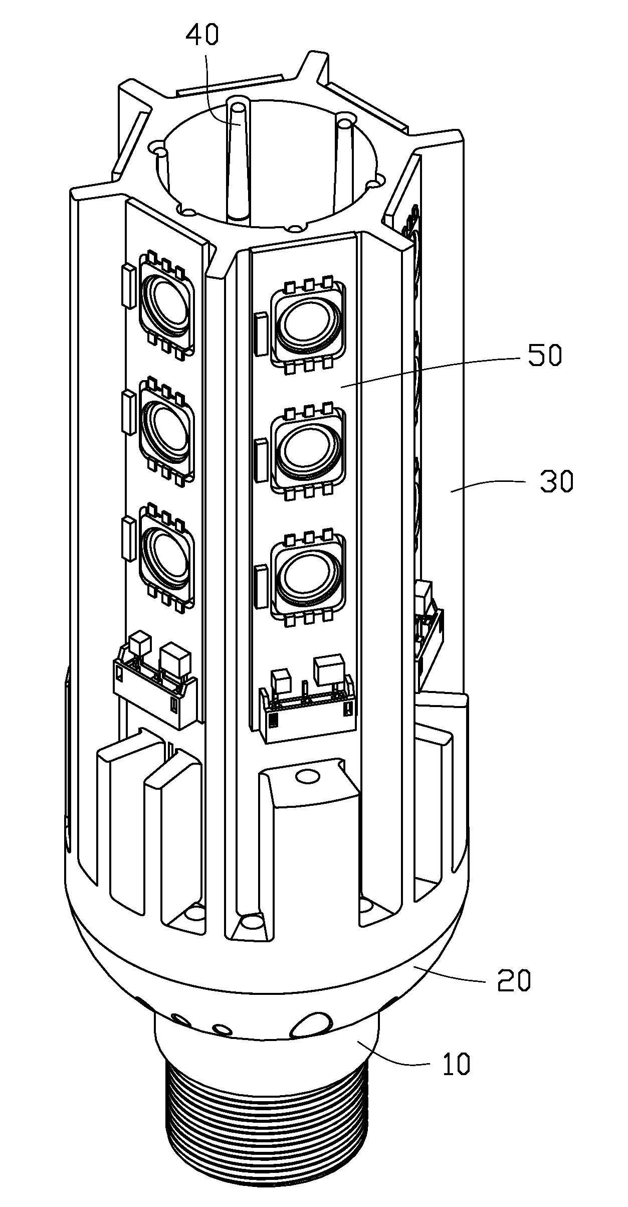
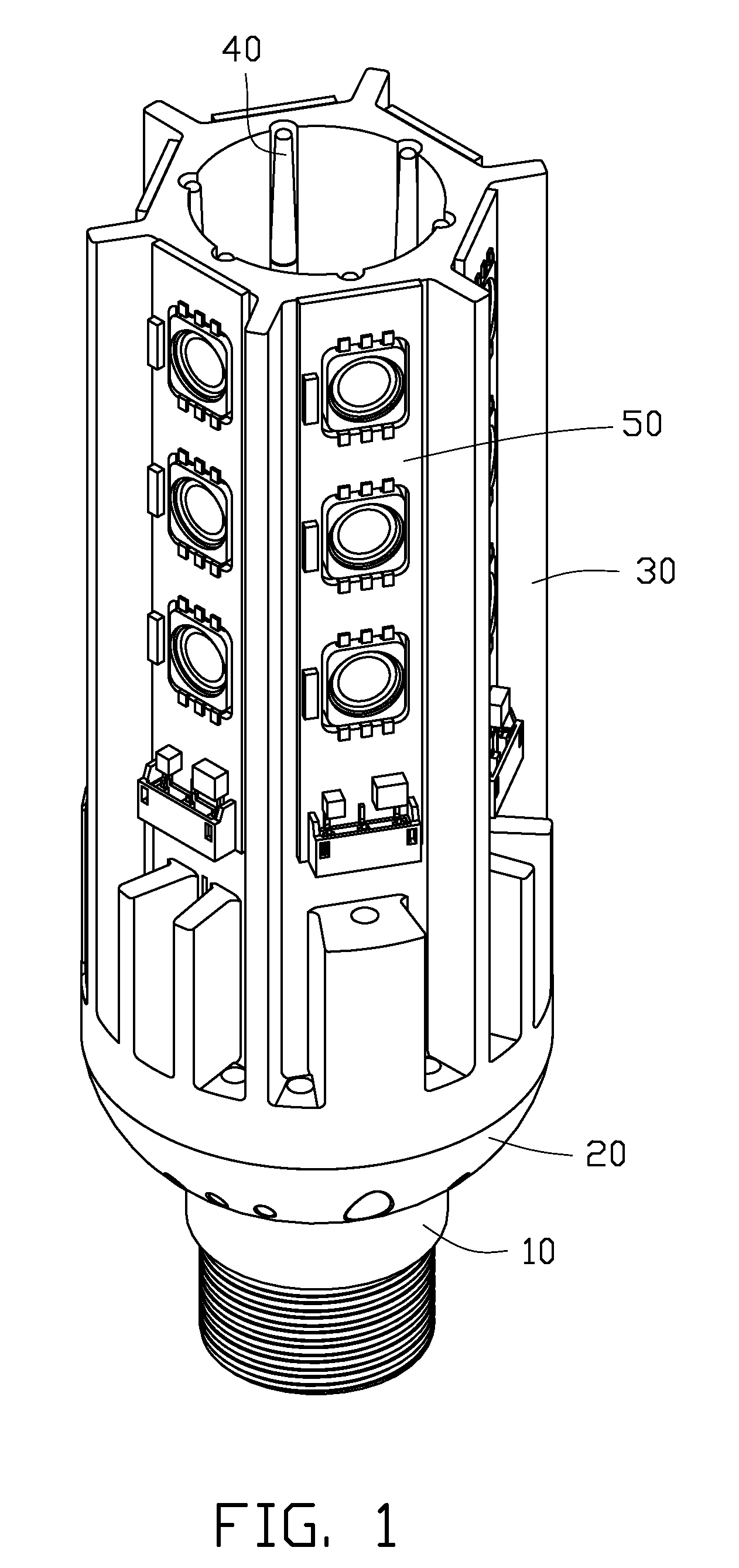
[0015]Referring to FIG. 1, an LED lamp adapted for a lighting purpose comprises a heat sink 30, a plurality of LED modules 50 mounted on periphery of the heat sink 30, a plurality of heat pipes 40 attached to interior of the heat sink 30, a cover 20 secured to a bottom portion of the heat sink 30, and a lamp seat 10 engaging with the cover 20.

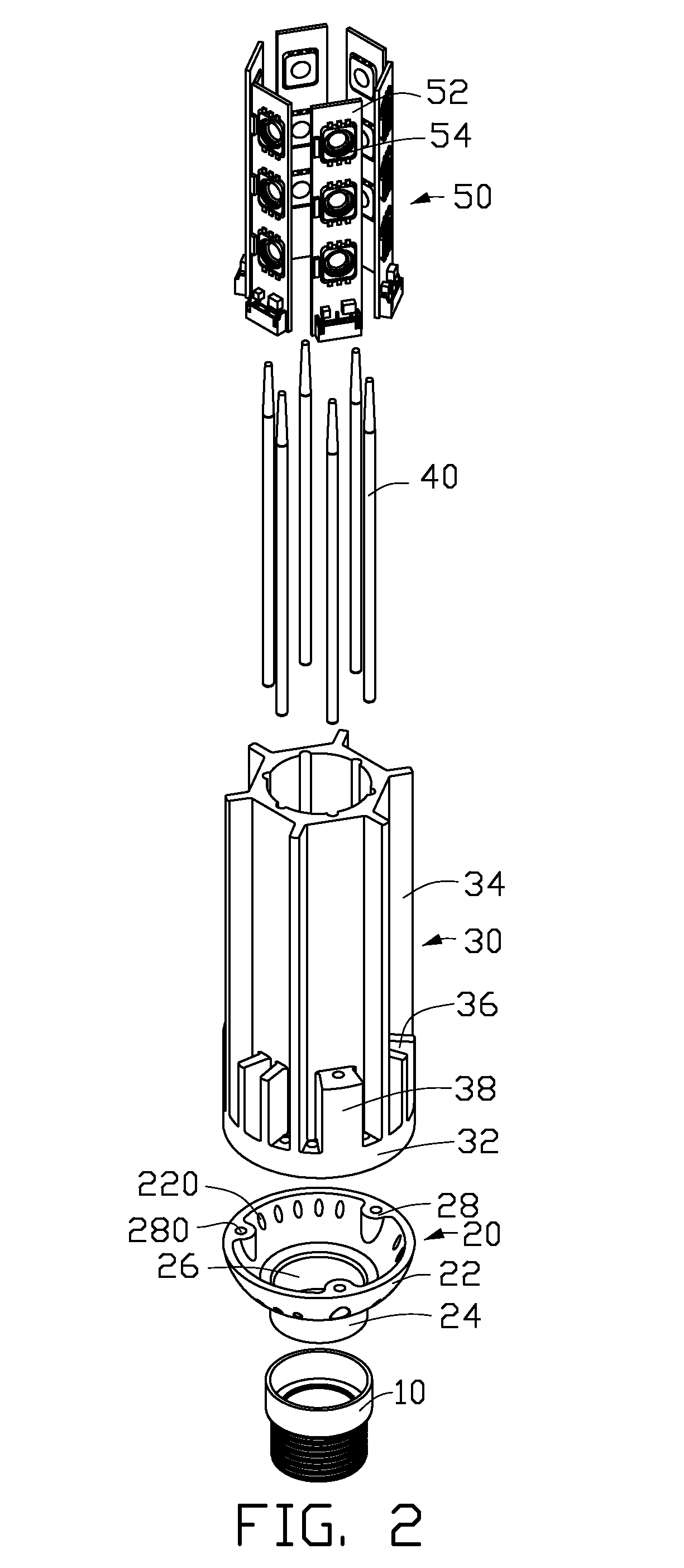
[0016]As shown in FIG. 2, the cover 20 comprises a bowl-shaped body 22. A through hole 26 is defined in a bottom portion of the body 22. An annular wall 24 extends from an edge of the bottom portion of the body 22 for engaging with the lamp seat 10. Three arced bulges 28 project evenly from an inner face at a top portion of the body 22 in a manner such that 120° angles are defined therebetween. Each bulge 28 has a planar top face that is in a common plane with a top face of the body 22. A through hole 280 with a larger bottom portion is defined at the top face of each bulge 28. A plurality of oval apertures 220 is evenly defined in a sidewall o...


PUM


Abstract

An LED lamp adapted for lighting includes a heat sink (30), a bowl-shaped cover (20) attached to a bottom portion of the heat sink, a lamp seat (10) secured below the cover, a plurality of LEDs (54) mounted on an outside surface of the heat sink, and a plurality of heat pipes (40) contacting with interior face of the heat sink. The heat sink has a plurality of fins (34, 36) extending from sidewalls thereof. The cover has a plurality of apertures (220) defined on lateral wall thereof. The heat generated by the LEDs can be transferred to the heat sink evenly via the heat pipes, and is then dispersed to ambient air efficiently and rapidly.

Description

BACKGROUND OF THE INVENTION[0001]1. Field of the Invention[0002]The present invention relates to a light emitting diode (LED) lamp, and more particularly to an LED lamp incorporating heat pipes for improving heat dissipation of the LED lamp.[0003]2. Description of Related Art[0004]LED (light emitting diode) lights are highly energy efficient electrical light sources, and are increasingly being considered for indoor lighting purposes. In order to increase the overall lighting brightness, a plurality of LEDs are often incorporated into a signal lamp, but these can lead to significant problems with over-heating.[0005]Conventionally, an LED lamp comprises a cylindrical enclosure functioning as a heat sink and a plurality of LEDs mounted on an outer wall of the enclosure. The LEDs are arranged in a plurality of lines along a lateral side of the enclosure and around the enclosure. The enclosure is open at one end. When the LEDs are activated, heat generated by the LEDs is dispersed to amb...

Claims


Application Information

Patent Timeline
IPC IPC(8): F21V29/00
CPCF21K9/00F21V29/83F21K9/135F21V29/777F21V29/006F21Y2101/02F21Y2111/005F21K9/232F21Y2115/10F21Y2107/30F21V29/51
Inventor ZHENG, SHI-SONGYU, GUANGHE, LI
Owner HON HAI PRECISION IND CO LTD
Why Eureka
Try Eureka