Digital single lens reflex camera

a single-lens reflex and camera technology, applied in the field of single-lens reflex cameras, can solve problems such as layout options

Inactive Publication Date: 2008-10-14
CANON KK
View PDF4 Cites 6 Cited by
  • Summary
  • Abstract
  • Description
  • Claims
  • Application Information

AI Technical Summary

Problems solved by technology

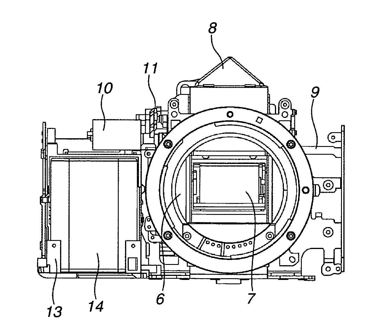
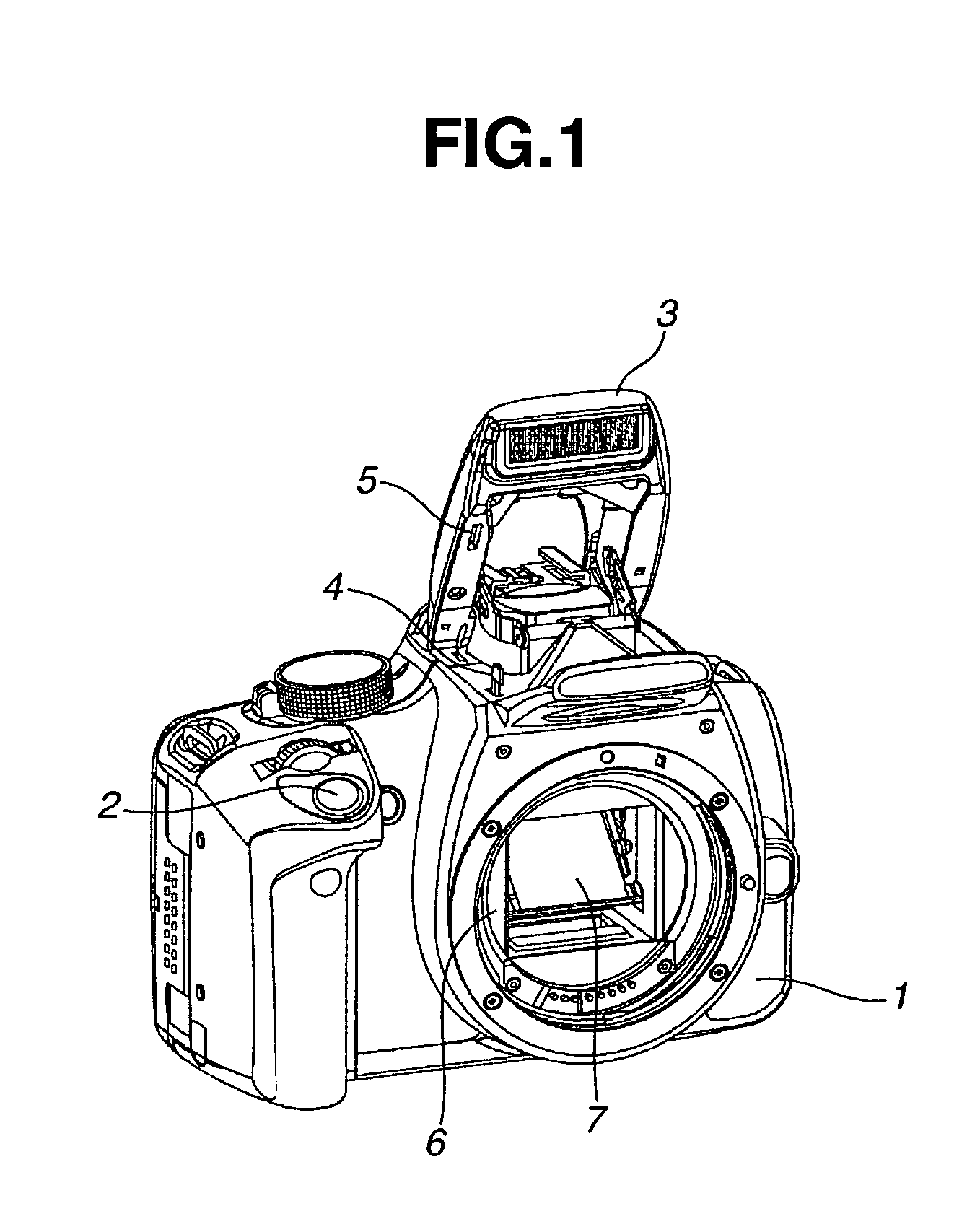
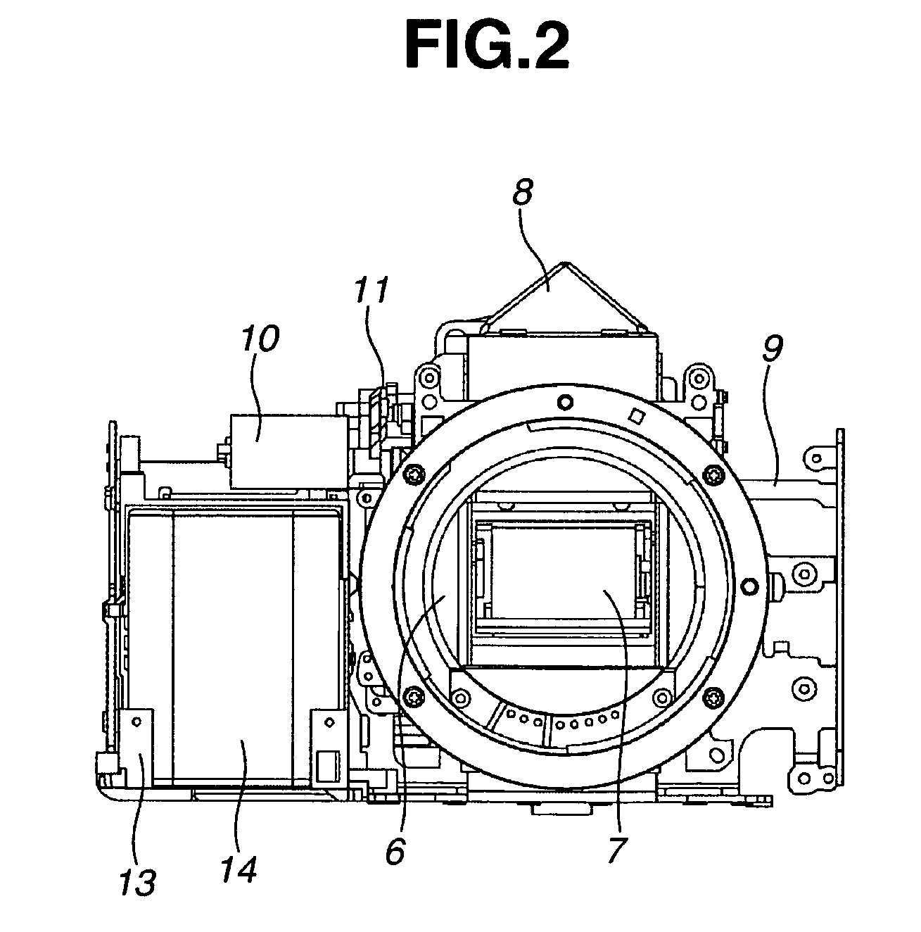
When reducing the size of the single lens reflex camera, the layout options for the constituent elements are limited due to the arrangement constrictions of a quick return mirror that guides the optical flux to the finder optical system and a mirror box that surrounds it.
However, the layout of elements constituting the digital camera inherits practices of the silver halide film single lens reflex camera, which are not suitable for the digital single lens reflex camera.

Method used


Image

  • Digital single lens reflex camera
  • Digital single lens reflex camera
  • Digital single lens reflex camera

Examples


Embodiment Construction

[0022]The following description of exemplary embodiment(s) is merely illustrative in nature and is in no way intended to limit the invention, its application, or uses.

[0023]Exemplary embodiments can be incorporated into various imaging devices (e.g., electronic cameras, camcorders, digital still cameras, film cameras, broadcast cameras, other imaging devices as known by one of ordinary skill, and equivalents).

[0024]Processes, techniques, apparatus, and materials as known by one of ordinary skill in the art may not be discussed in detail but are intended to be part of the enabling description where appropriate. For example, lens and lens units are discussed and any material that can be used to form lenses should fall within the scope of exemplary embodiments (e.g., glass, Si). Additionally the actual size of the lens may not be discussed however any size from macro lenses to nano lenses are intended to lie within the scope of exemplary embodiments (e.g., lenses with diameters of nano...


PUM


Abstract

At least one exemplary embodiment is directed to a digital single lens reflex camera which includes a motor on a side of a mirror box above a battery storage unit for a detachable battery, such that the motor's output shaft can be substantially perpendicular to the optical axis, which facilitates reduction of the size of the entire camera.

Description

BACKGROUND OF THE INVENTION[0001]1. Field of the Invention[0002]The present invention relates to a single lens reflex camera. Particularly, though not exclusively, the invention relates to positioning a motor for driving a quick return mirror.[0003]2. Description of the Related Art[0004]Various proposals are made about how to dispose in the single lens reflex camera the constituent elements such as motors and capacitors in order to reduce its size.[0005]For example, Japanese Utility Model Application Laid-Open No. 2-39236 discusses a single lens reflex camera where the motor is disposed in a spool room on a side of a mirror box such that its output shaft intersects with an optical axis.[0006]Japanese Patent Application Laid-Open No. 9-80603 discusses a configuration that separately lays out the same kinds of constituent elements. That is, one of the cylindrical capacitors for driving a built-in flash unit is disposed inside a camera grip together with a battery, and other cylindrica...

Claims


Application Information

Patent Timeline
Patent Type & Authority Patents(United States)
IPC IPC(8): G03B19/12G03B15/03H04N5/222G03B17/02
CPCG03B17/02G03B19/12G03B2215/0507
Inventor TSUKATANI, EIRI
Owner CANON KK
Why Eureka
Try Eureka