Self-cleaning paint roller

a self-cleaning, paint roller technology, applied in the direction of coatings, printing, spraying apparatus, etc., can solve the problems of time-consuming and messy processes, inconvenient hannah system, and the need to remove the roller sleeves from the roller, so as to reduce the time spent cleaning, quick and easy paint, and the effect of quick and easy system

Active Publication Date: 2008-10-14
ATTERBURY THOMAS W
View PDF27 Cites 6 Cited by
  • Summary
  • Abstract
  • Description
  • Claims
  • Application Information

AI Technical Summary

Benefits of technology

[0015]This object is achieved by providing a self-cleaning paint roller system having a handle portion, a frame, a roller carrier rotatably carried by the roller for releasably receiving a roller sleeve, and an integral means for cleaning the roller sleeve without having to remove the roller sleeve from the roller carrier.
[0016]The present invention provides significant advantages, including: (1) combining a paint roller and a cleaning apparatus into a single device; (2) drastically reducing the time spent cleaning roller sleeves; (3) providing a system that allows a user to quickly and easily paint with one color, clean the roller sleeve, and immediately begin painting with another color with the same roller sleeve, without having to remove the roller sleeve from the roller; (4) providing a quick and easy system for cleaning roller sleeves for both conventional, non-self cleaning paint rollers and self-cleaning paint rollers; and (5) conserving water and / or cleaning solution use during the cleaning process.

Problems solved by technology

Although these types of cleaning methods have some advantages, there are significant disadvantages associated with each method.
With regard to the first method of cleaning roller sleeves, the main disadvantage is that the roller sleeve must be removed from the roller, which is a time consuming and messy processes.
The Hannah system is inconvenient because a user must first handle the paint-filled roller sleeve to insert it into the housing.
With regard to the second method of cleaning roller sleeves, the main disadvantage is that the cleaning device is a separate apparatus that must be stored, cleaned, transported, and made available at the job location.
This system is inconvenient because the cleaner is a separate and distinct tool from the paint roller.
If the van Rooyen system is inadvertently left away from the painting location where the paint-filled roller sleeves need to be cleaned, the user must either transport the paint-filled roller sleeves to the cleaning device or forego cleaning the applicators.
This delay in cleaning the roller sleeve is problematic, because the roller sleeves become permanently damaged if the paint is not removed before the paint is allowed to dry.
With regard to the third method of cleaning roller sleeves, the main disadvantage is that the user must handle the paint-filled roller sleeve and the cleaning shield.
The Faustman device is inconvenient, because the user must handle both the paint-filled roller sleeve, the attached cleaning structure, and a water hose to implement the system.
Therefore, the user is placed in very close proximity to the cleaning structure and is very likely to get sprayed with paint and water.
In addition to the above described disadvantages, all of the above methods of cleaning roller sleeves further share a number of additional disadvantages.
One disadvantage in common to all of the above methods is that none of them are designed to reduce water and cleaning solution consumption.
The above methods of cleaning roller sleeves are not well suited for cleaning roller sleeves quickly and for the purpose of using the roller sleeves again during the same painting process.
The above methods of cleaning roller sleeves typically take long periods of time to fully clean the roller sleeves.
For example, the above methods are not well suited for multiple quick cleaning of the roller sleeves in some of the above methods because the roller sleeve must be removed from the paint roller and placed within a separate cleaning mechanism, taking additional time.
Again, where the roller sleeve and frame must be inserted into a separate apparatus for cleaning, the paint roller may need to be transported to the location of the cleaning apparatus, taking additional time.
Another disadvantage shared by all of the above methods for cleaning roller sleeves is that they include complicated steps and require training to use the cleaning devices.
Many of the steps above are difficult and cost the user additional time.

Method used


Image

  • Self-cleaning paint roller
  • Self-cleaning paint roller
  • Self-cleaning paint roller

Examples


Embodiment Construction

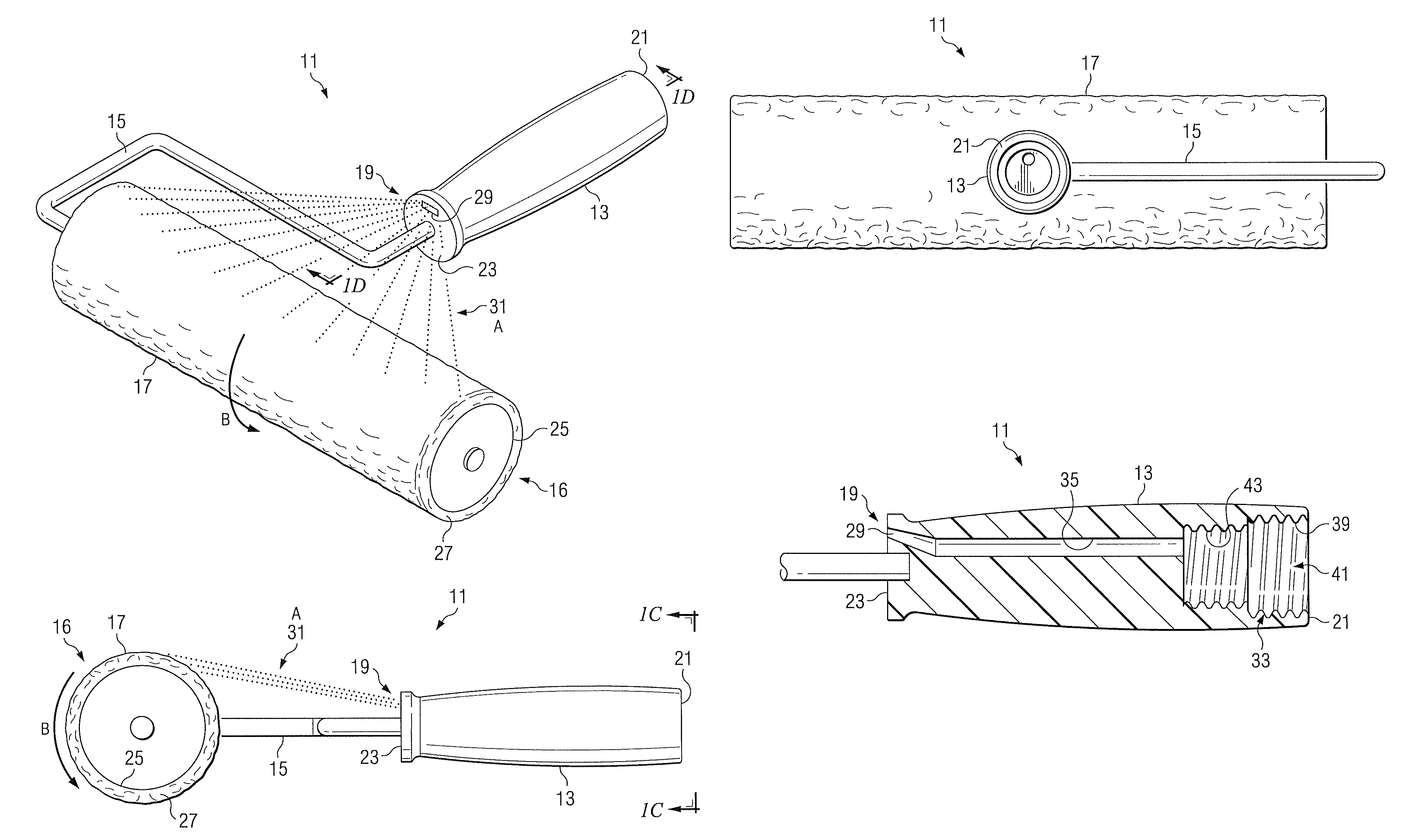
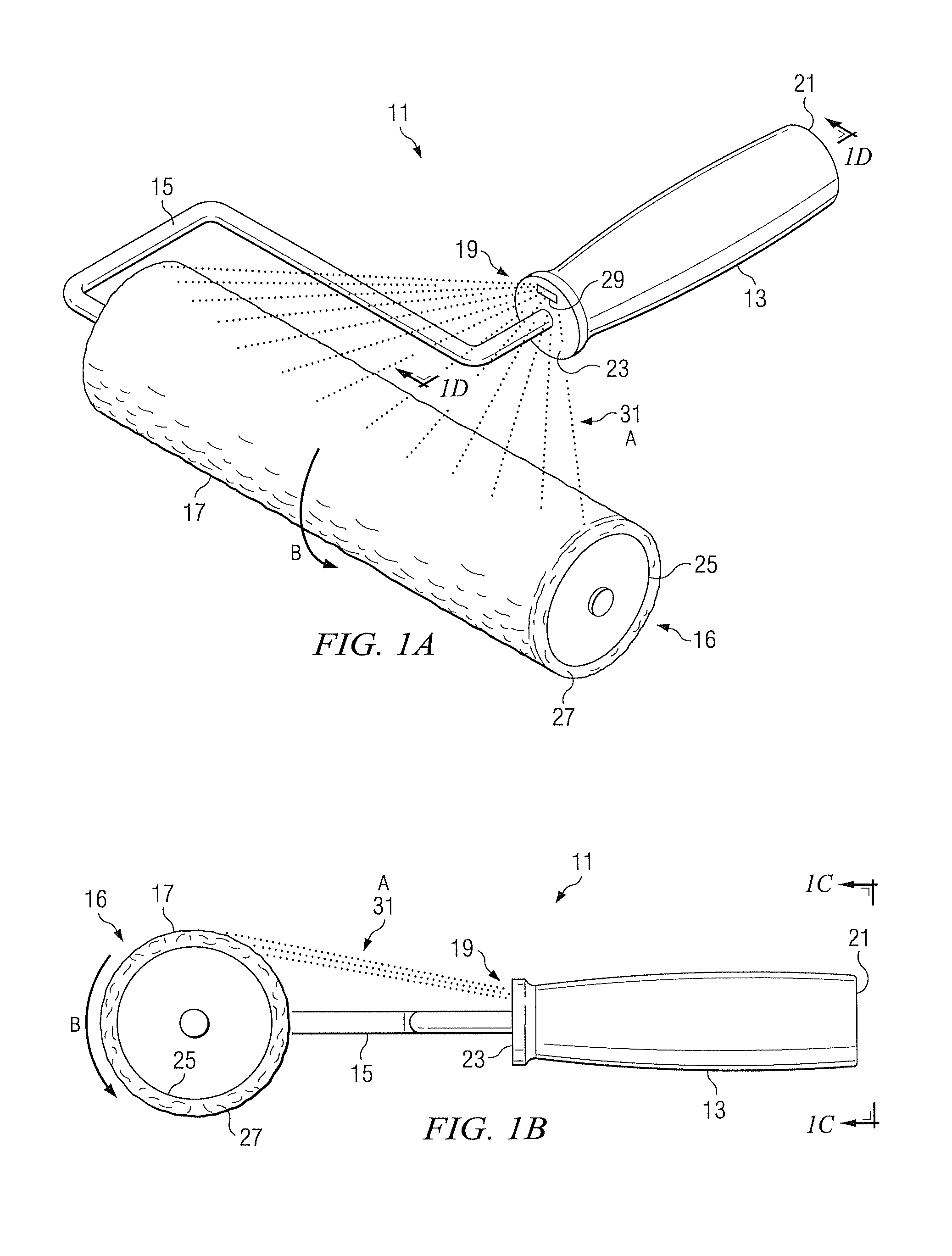
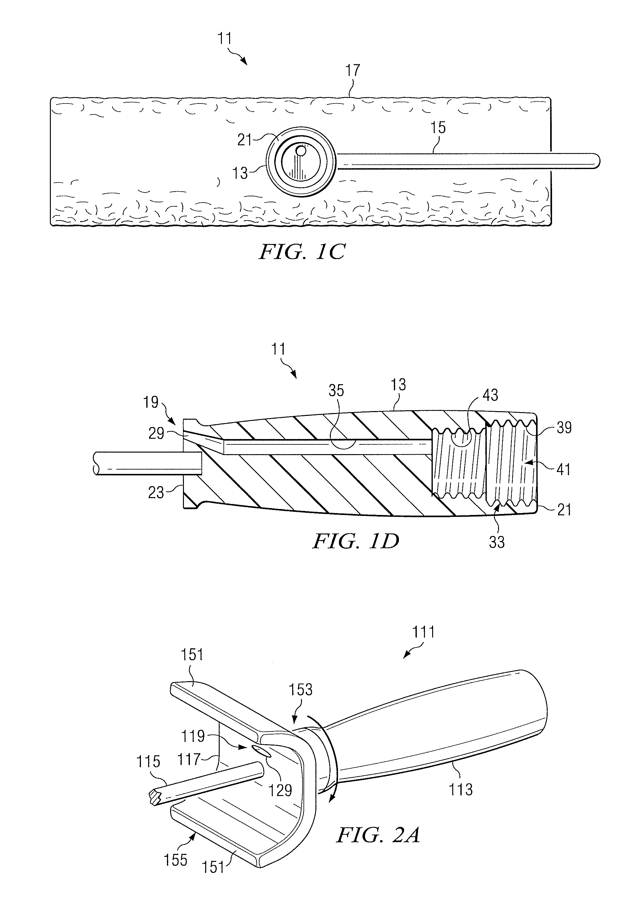
[0045]Referring now to FIGS. 1A-1D in the drawings, the preferred embodiment of a self-cleaning paint roller assembly 11 according to the present invention is illustrated. Paint roller assembly 11 preferably comprises a handle 13, a frame 15 coupled to handle 13, a roller 16 rotatably carried by frame 15, and an integral cleaning means 19. Handle 13 has a proximal end 21 and a distal end 23. Although handle 13 is illustrated as a solid grippable elongate member, it will be appreciated that handle 13 may be alternatively be shaped and configured. Roller 16 is adapted to slidingly receive a roller sleeve 17 that is adapted to receive and distribute paint. Roller 16 may include a means for latching and / or centering roller sleeve 17. When assembled onto paint roller assembly 11, roller sleeve 17 is free to rotate about a portion of frame 15. Although frame 15 is shown bent or angled such that roller 16 is substantially transverse to handle 13, it should be understood that frame 15 may a...


PUM


Abstract

A self-cleaning paint roller has a handle, a frame for carrying a roller sleeve attached to the handle, and a cleaning portion for cleaning a roller sleeve carried by the frame.

Description

BACKGROUND OF THE INVENTION[0001]1. Field of the Invention[0002]The present invention relates to paint rollers and to the cleaning of paint roller sleeves.[0003]2. Description of Related Art[0004]Conventional paint rollers typically comprise a handle, a support frame attached to the handle, a roller rotatably carried by the frame. The roller is adapted to releasably receive a roller sleeve for applying paint to a surface. Although with some paint rollers the roller and the roller sleeve form a single component, most paint rollers are designed for use with removable roller sleeves. After using a paint roller, it is often desirable to clean the roller sleeve so that it can be used again. This is particularly true for high-end roller sleeves made of lamb's wool that are intended to be reused again and again.[0005]There are many ways to clean roller sleeves; however, most methods fall into one of three categories: (1) removing the roller sleeve from the roller; (2) inserting the frame, ...

Claims


Application Information

Patent Timeline
Patent Type & Authority Patents(United States)
IPC IPC(8): B43M11/02
CPCB05B15/02B05C17/0205B05C17/035B44D3/006B05B15/50
Inventor ATTERBURY, THOMAS W.
Owner ATTERBURY THOMAS W
Why Eureka
Try Eureka