Prosthesis and a method and means of deploying a prosthesis

a technology of prosthesis and prosthesis, which is applied in the field of prosthesis and a method and means of deploying a prosthesis, can solve the problems of null and void entire deployment, no possible control of the position of the distal end of the graft, and no control of the position of the prosthesis at either end

Inactive Publication Date: 2008-10-14
WILLIAM A COOK AUSTRALIA
View PDF27 Cites 225 Cited by
  • Summary
  • Abstract
  • Description
  • Claims
  • Application Information

AI Technical Summary

Benefits of technology

[0022]In an alternate form the invention may be said to reside in an introducer adapted for the introduction of a self expanding endovascular prosthesis into a lumen of a patient, the prosthesis having a proximal end and a distal end, the introducer comprising, a proximal attachment device adapted to be attached to the proximal end of the prosthesis, a distal attachment device adapted to be attached to the distal end of the prosthesis, each of the proximal an...

Problems solved by technology

After the graft has been released there is no possible control of the position of the distal end of the graft.
Inadequate placement can render the entire deployment null and void.
Once again after the prosthesis has been released by removal of the sheath there is no possible control of the position of the either end of the prosthesis.
This system provides very little control over the deplo...

Method used


Image

  • Prosthesis and a method and means of deploying a prosthesis
  • Prosthesis and a method and means of deploying a prosthesis
  • Prosthesis and a method and means of deploying a prosthesis

Examples


Embodiment Construction

[0054]The construction of preferred embodiments and the method by which the device may be operated may be made clearer with the aid of the accompanying drawings which show preferred embodiments of the invention and the method by which the device of the various embodiments may be used. For the purpose of clarity the lumens or vessels into which the prosthesis has to be inserted is not been shown in the drawings except in FIG. 18.

[0055]In the drawings:

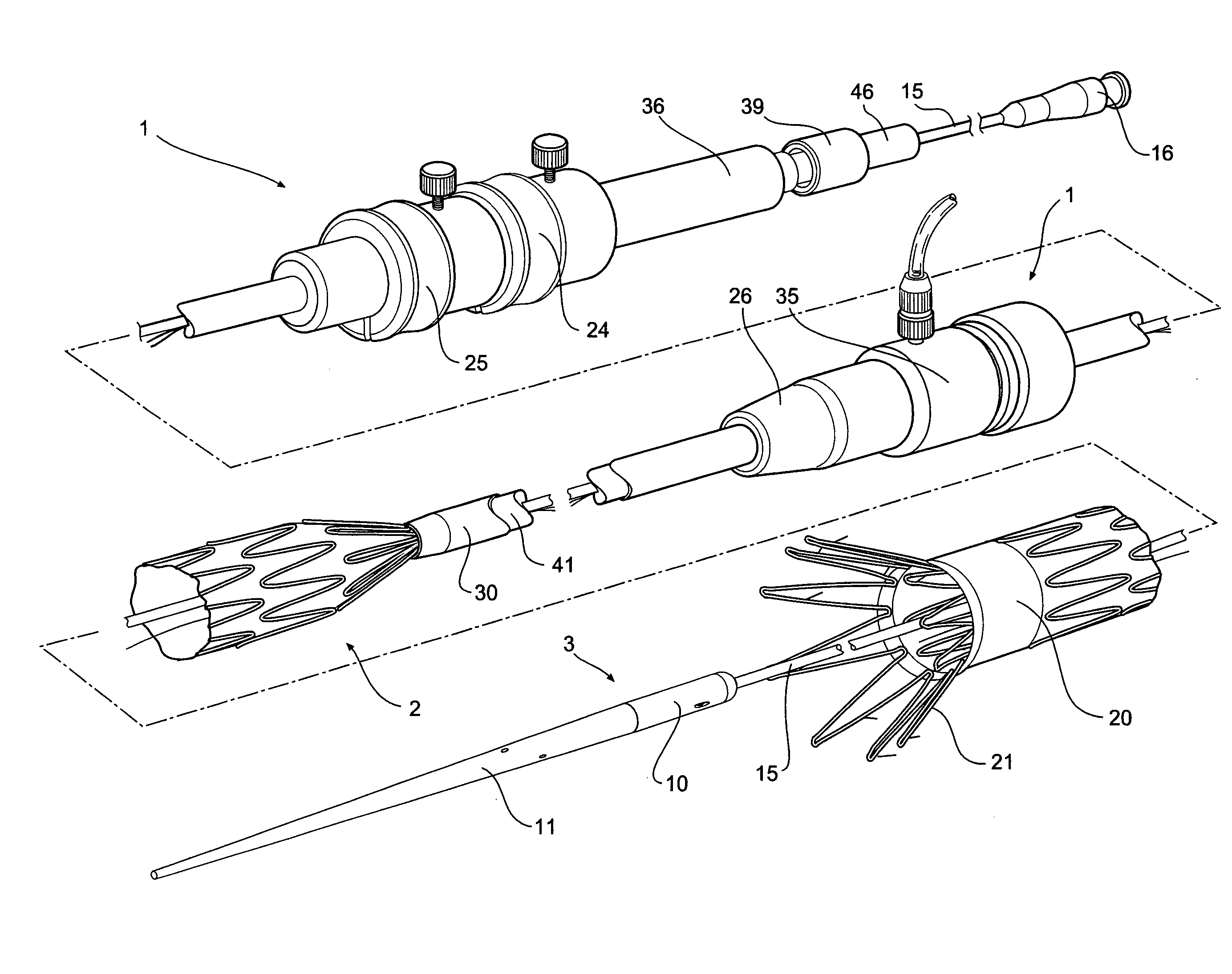
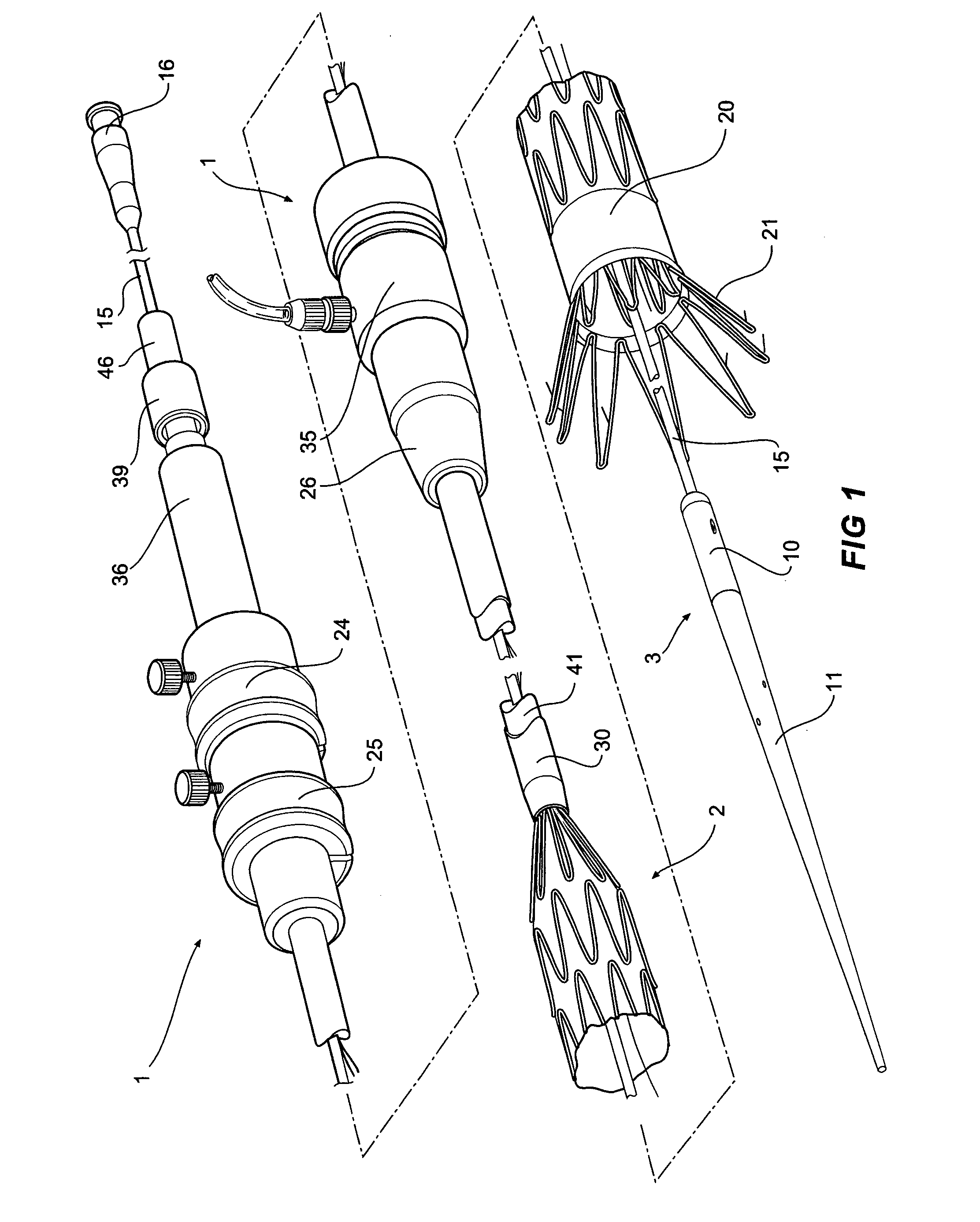
[0056]FIG. 1 shows a first embodiment of an introducer according to this invention in perspective view with the prosthesis partially deployed,

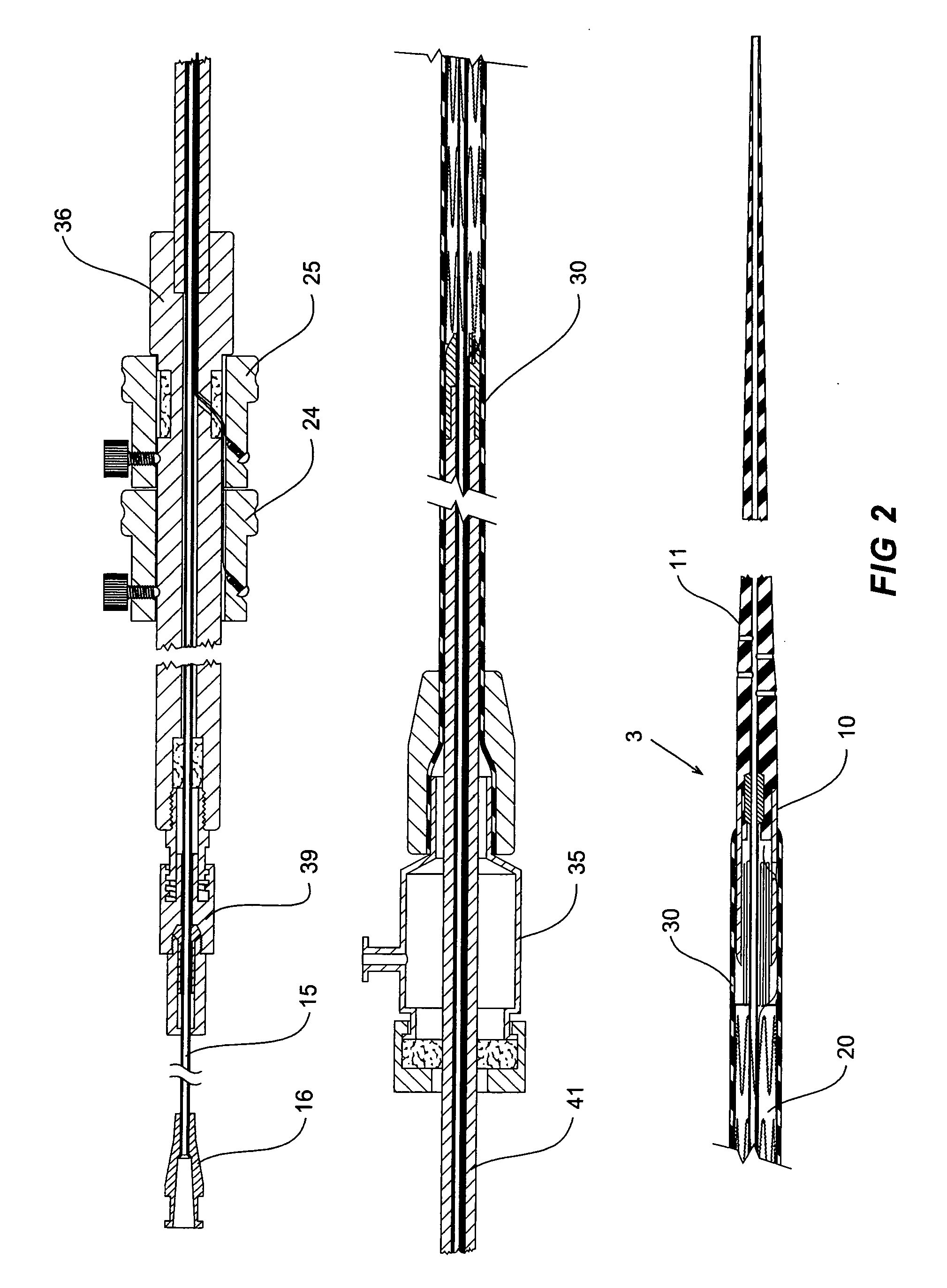
[0057]FIG. 2 shows the first embodiment of the introducer as shown in FIG. 1 being fully loaded and ready for introduction into a patient,

[0058]FIG. 3 shows the embodiment of FIG. 2 in the next stage of deployment of the prosthesis,

[0059]FIG. 4 shows the embodiment of FIG. 2 with the release of the proximal end stage of deployment,

[0060]FIG. 5 shows the release of the distal end stage of deployment...


PUM


Abstract

An introducer (1) adapted for the introduction of a self-expanding endovascular prosthesis (20) in a lumen of a patient. The introducer has attachment devices (10,30) to hold each end of the prosthesis so that each can be moved independently. An end ovascular prosthesis (20) is also claimed with stents at the proximal and distal ends being within the graft. The remainder of the stents are positioned on the outside of the graft body.

Description

CROSS REFERENCE TO RELATED COPENDING APPLICATION[0001]This application is a continuation of International Application Number PCT / AU98 / 00383 filed May 25, 1998 and Australian Application Number PO 7008 filed May 26, 1997.FIELD OF INVENTION[0002]This invention relates to an method and means for introducing an expandable intraluminal prosthesis which may be straight, tubular or bifurcated in form and intended for the endovascular repair of diseased or damaged vessels and to a prosthesis which is suitable for such a procedure.[0003]Throughout this specification the terms proximal and proximally are used for a position or direction towards the patient's heart and the terms distal and distally are used for a position or direction away the patient's heart.BACKGROUND OF THE INVENTION[0004]The deployment of intraluminal prostheses into the lumen of a patient from a remote location by the use of a deployment device or introducer, has been disclosed in a number of earlier patent specifications...

Claims


Application Information

Patent Timeline
IPC IPC(8): A61F2/06A61F2/07A61F2/89A61F2/95A61F2/954A61F2/958A61F2/966A61M29/00
CPCA61F2/07A61F2/954A61F2/958A61F2/966A61F2002/065A61F2002/075A61F2230/0067A61F2002/9517A61F2002/9665A61F2/89A61F2230/005A61F2230/0054A61F2002/9511A61F2/9517
Inventor HARTLEY, DAVIDLAWRENCE-BROWN, MICHAEL
Owner WILLIAM A COOK AUSTRALIA
Why Eureka
Try Eureka