
Endoscopic band ligator

a band ligator and endoscope technology, applied in the field of medical ligating instruments, can solve the problems of physician inability to operate, device could not release any band at the location, and the control handle of operating ligating devices is somewhat primitive, so as to achieve the effect of simplifying inputs

Inactive Publication Date: 2007-11-15
COMMAND ENDOSCOPIC TECH
View PDF25 Cites 15 Cited by
  • Summary
  • Abstract
  • Description
  • Claims
  • Application Information

AI Technical Summary

Benefits of technology

"The invention is an endoscopic accessory that attaches to a viewing endoscope and is used to apply ligating bands to tissue areas. It is useful in treating tissue areas accessible through a natural body lumen or cavity such as esophageal varices. The device comprises three coaxially arranged cylinders that can be slid relative to each other to create a vacuum chamber for aspirating tissue and to dispense a ligating band. The device is easy to operate with one hand and can be remotely controlled. The invention also provides a method for endoscopically applying multiple ligation bands with simplified inputs."

Problems solved by technology

Because of inherent inaccuracies in the remote operation of the outer cylinder, more than one band could be inadvertently released at a single site or the device could fail to release any bands at the location.
Further frustrating this problem is the fact that the physician may not realize that a single band is not successfully released at the desired location.
Control handles for operating ligating devices has been somewhat primitive and may require two hands to operate.
Two handed operation of the ligator control handle is especially problematic in endoscopic context because at least one hand must be used to operate endoscope controls for articulating the distal end of the endoscope so that it may be properly navigated.
Cable operated band dispensers lose tactile feel and accurate movement due to the flexibility inherent in the cable and in the unstable sliding movement of the small ligator components that move to release the bands.

Method used


Image

  • Endoscopic band ligator
  • Endoscopic band ligator
  • Endoscopic band ligator

Examples


Embodiment Construction

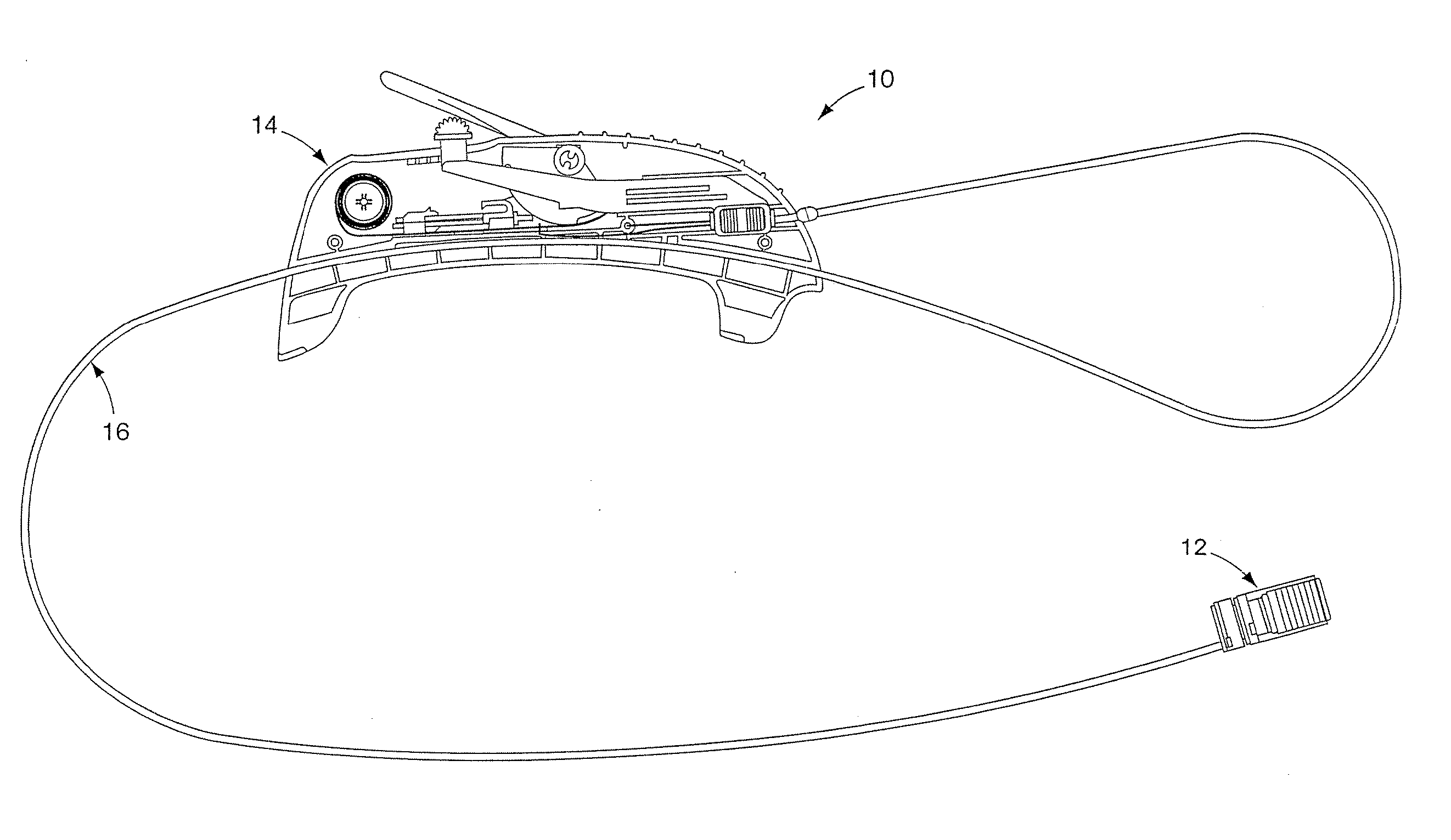
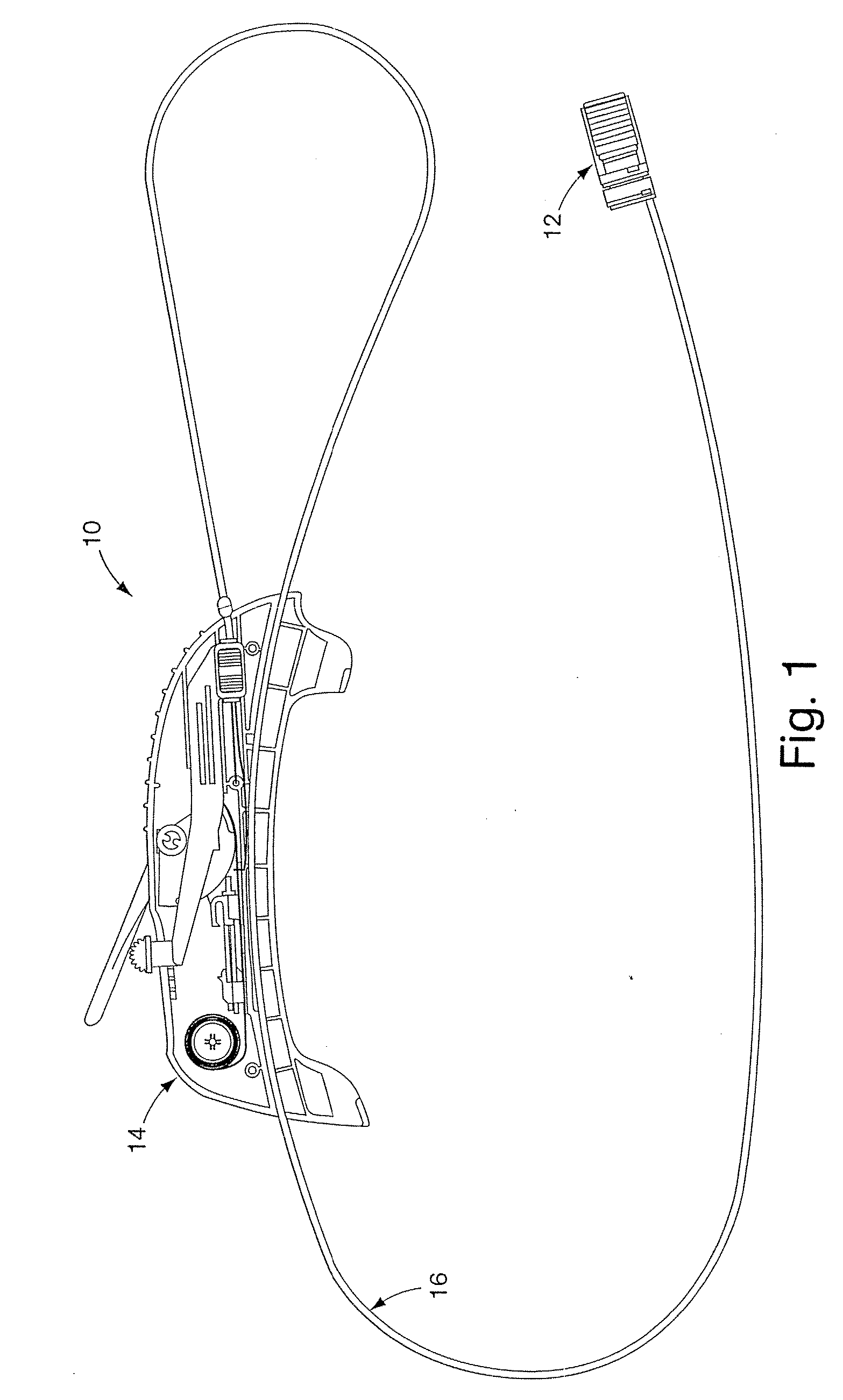
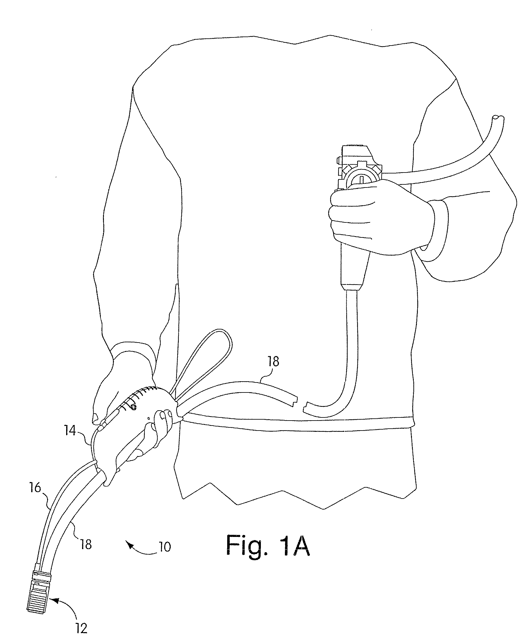
[0044] The band ligator 10, shown in FIG. 1, comprises a working distal portion 12 joined to a control handle 14 via a control sheath 16. The distal portion 12 may be removably mounted to the exterior surface of the distal end of the endoscope. The distal portion 12 is configured to deliver ligating bands to internal tissue locations, such as at varices in order to prevent bleeding at those sites. The distal portion is operated by control wires slidable through sheath 16, which extends proximally, external to the endoscope to the control handle 14. The handle is slidably and removably attached to the exterior of the endoscope shaft. The ligator device is configured to minimize interference with the viewing capability of the endoscope: utilizing transparent components and a retracted mounting configuration on the scope that avoids obstruction of the distal face and viewing lens during navigation to a treatment site.

[0045] In an exemplary use of the device 10 such as treatment of eso...


PUM


Abstract

The present invention provides a ligating band dispenser that is mounted on the distal end of an endoscope. The ligator is configured to deliver multiple ligating bands to a plurality of internal sites in a patient. The ligating bands are carried on a tubular band carrier member that is retractable relative to the distal end of the endoscope in order to preserve visibility through the endoscope during navigation, then extendable to define a suction chamber for tissue aspiration during band delivery. A tubular band driver member is slidable over the band carrier member and engages bands individually to push them off the distal end of the band carrier and onto a selected treatment site. A single-hand operated control handle for selectively operating the extension of the band carrier and movement of the band driver to release a band is also provided and is slidably and removably mounted to the endoscope shaft.

Description

CROSS-REFERENCE TO RELATED APPLICATION [0001] This application is a divisional of U.S. patent application Ser. No. 10 / 656,083, filed Sep. 5, 2003, now U.S. Pat. No. 7,189,247, issued Mar. 13, 2007, which claims priority to U.S. Provisional Application Ser. No. 60 / 408,555, filed Sep. 6, 2002.FIELD OF THE INVENTION [0002] The present invention relates to medical ligating instruments. In particular, the invention relates to multiple band endoscopic band ligating devices. BACKGROUND OF THE INVENTION [0003] Ligation is a procedure in which a thread, wire or band are applied around a tissue structure or area to constrict it thereby preventing flow of blood or other body fluids. Band ligation involves applying a highly elastic band around a tissue site to constrict it. Ligation may be used to treat varices, polyps, hemorrhoids, or other lesions. After application of a ligator at the treatment site, bleeding is stopped and the tissue below the ligature then begins to heal and fuse together ...

Claims


Application Information

Patent Timeline
Patent Type & Authority Applications(United States)
IPC IPC(8): A61B17/94A61BA61B17/12A61B1/00A61B17/04
CPCA61B1/00087A61B2017/12018A61B2017/00296A61B17/12013
Inventor ZIRPS, CHRISTOPHER T.MEMBRINO, TIMOTHY R.REED, SCOTTCORRAO, ERNEST JR.MAGUIRE, STEPHENMEARS, ERICCOPELAND, DAVID J.MURPHY, JOHN S.LOGAN, JOSEPHSILVA, SEAN J.YARDAN, STEPHEN J.
Owner COMMAND ENDOSCOPIC TECH
Learn More