
Angular velocity sensor and method for manufacturing the same

a technology of angular velocity sensor and manufacturing method, which is applied in the direction of generator/motor, turn-sensitive device, instruments, etc., can solve the problem of unnecessary vibration components

Inactive Publication Date: 2008-10-14
PANASONIC CORP
View PDF14 Cites 19 Cited by
  • Summary
  • Abstract
  • Description
  • Claims
  • Application Information

AI Technical Summary

Benefits of technology

[0031]An angular velocity sensor of the present invention includes a tuning fork vibrator having two arms and a base to support the two arms together. It also includes a drive unit formed on a main surface of each of the two arms in order to drive each of the two arms in the X-axis direction. It also includes a detection unit formed on a main surface of each of the two arms in order to detect the vibration of each of the two arms in the Z-axis direction based on an angular velocity Ω applied around the Y-axis. The detection unit is made by forming a bottom electrode on the main surface of each of the two arms, and by further forming a piezoelectric film and a top electrode in this order on the bottom electrode. The main surface of each of the two arms and a tilted side surface adjacent to the main surface cross each other at an acute angle. This allows the center of at least the top electrode of the detection unit to be shifted from the center of the main surface of each of the two arms to the side opposite to the tilted side surface. As a result, the angular velocity sensor can control the generation of signals which are unnecessary to the angular velocity sensor and are generated on the sensing electrodes when the tuning fork is made to vibrate in the X-axis direction, while maintaining the advantages of being thin and requiring no individual adjustment of the vibrator.
[0032]In an angular velocity sensor of another aspect of the present invention, the main surface of each of the two arms having the detection unit thereon and a tilted side surface adjacent to the main surface cross each other at an acute angle. As a result, the center of at least the top electrode of the detection unit can be shifted by a specified amount towards the side surface opposite to the tilted side surface, that is, towards the vertical side surface in accordance with the degree of tilt of the tilted side surface. This improves the control of the generation of signals which are unnecessary to the angular velocity sensor and are generated on the sensing electrodes.
[0033]An angular velocity sensor of another aspect of the present invention includes a tuning fork vibrator having two arms and a base to support the two arms together. It also includes a drive unit formed on a main surface of each of the two arms in order to drive each of the two arms in the X-axis direction. It also includes a detection unit formed on a main surface of each of the two arms in order to detect the vibration of each of the two arms in the Z-axis direction based on an angular velocity applied around the Y-axis. The detection unit is made up of a bottom electrode formed on the main surface of each of the two arms, a piezoelectric film formed on the bottom electrode and a top electrode formed on the piezoelectric film. The main surface of each of the two arms having the detection unit thereon and a tilted side surface adjacent to the main surface cross each other at an obtuse angle. This allows the center of at least the top electrode of the detection unit to be shifted towards the tilted side surface. As a result, the angular velocity sensor can control the generation of signals which are unnecessary to the angular velocity sensor and are generated on the sensing electrodes when the tuning fork is made to vibrate in the X-axis direction, while maintaining the advantages of being thin and requiring no individual adjustment of the vibrator.

Problems solved by technology

As a result, when vibrating in the X-axis direction, the tuning fork vibrators formed far from the center of wafer 103 inevitably cause unnecessary vibration components in a direction (the Z-axis direction) other than the direction in which to vibrate the tuning fork vibrators.

Method used


Image

  • Angular velocity sensor and method for manufacturing the same
  • Angular velocity sensor and method for manufacturing the same
  • Angular velocity sensor and method for manufacturing the same

Examples


Embodiment Construction

[0094]An embodiment of the present invention will be described as follows with reference to drawings.

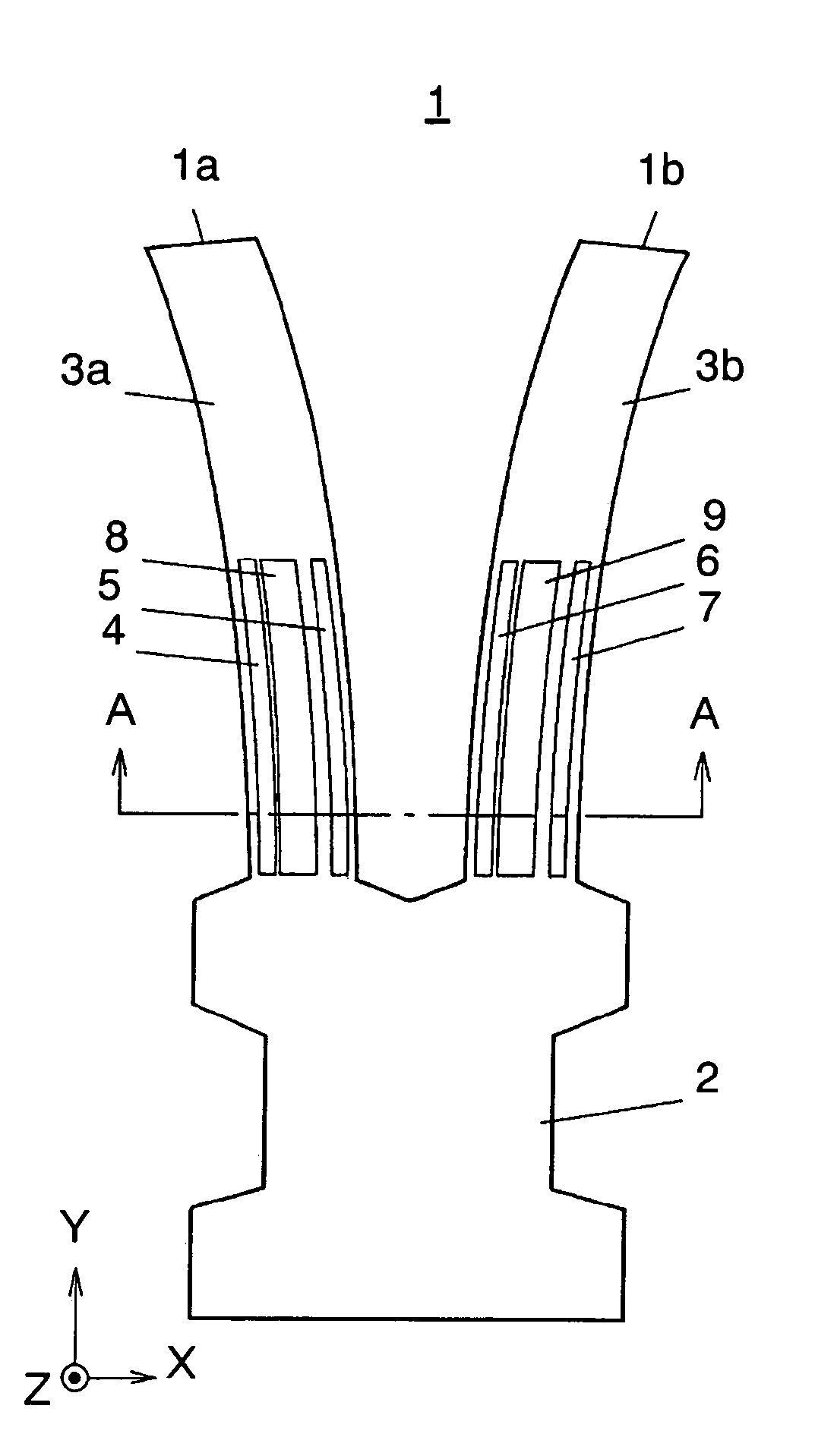
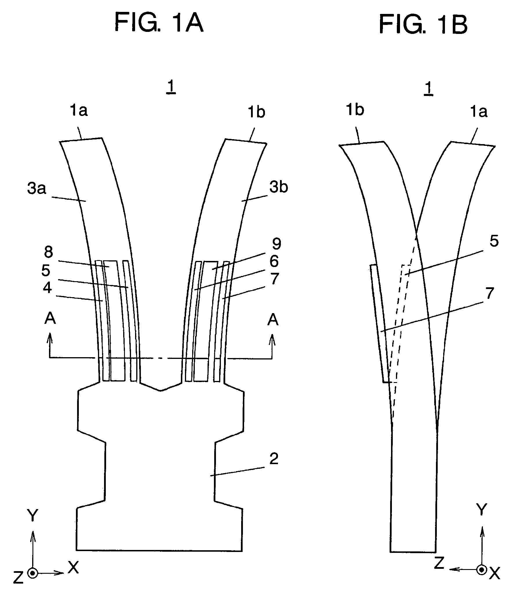
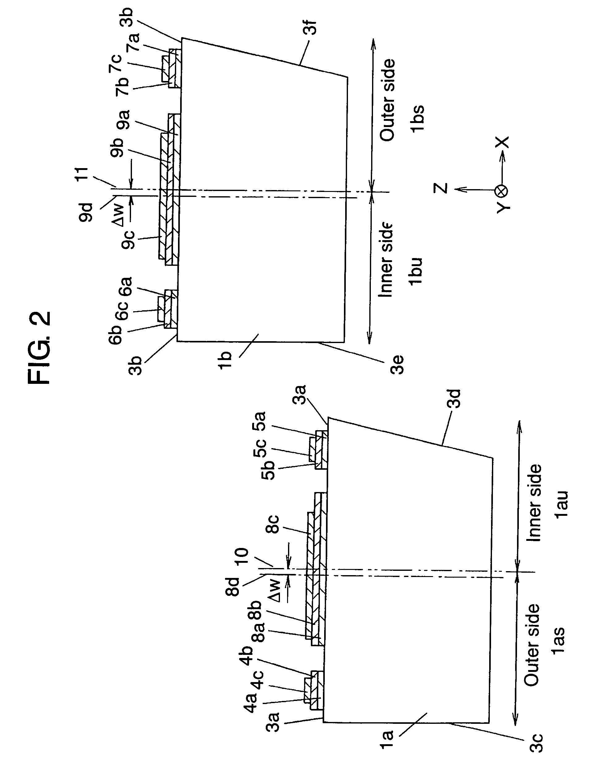
[0095]FIG. 1A is a plan view showing a tuning fork vibrator of an angular velocity sensor according to an embodiment of the present invention when it is driven in the X-axis direction; FIG. 1B is a side view of FIG. 1A; FIG. 2 is a cross sectional view taken along the line A-A of FIG. 1A; and FIG. 3 is an arrangement of tuning fork vibrators formed in the wafer according to the first embodiment. FIG. 4 is a flowchart showing the manufacturing processes on the cross section taken along the line B-B shown in FIG. 3. FIG. 5 shows manufacturing processes of the angular velocity sensor according to the present invention. FIG. 6 is a characteristic view to show the relationship between the positions of the tuning fork vibrators formed in the wafer in the X-axis direction by the manufacturing processes and the unnecessary signals generated on the sensing electrodes of the tuning fork vibrat...


PUM


Abstract

Provided is an angular velocity sensor which is thin, requires no individual adjustment and can control the generation of signals that are unnecessary to the angular velocity sensor and are generated on the sensing electrodes when the tuning fork is made to vibrate in the X-axis direction, and a method for manufacturing the angular velocity sensor. Centers (8d) and (9d) of top electrodes (8c) and (9c) as components of detection units are shifted by ΔW from centers (10) and (11) of main surfaces (3a) and (3b) of arms (1a) and (1b) of the tuning fork vibrator towards side surfaces (3c) and (3e) adjacent to main surfaces (3a) and (3b), respectively.

Description

[0001]This application is the U.S. National Phase under 35 U.S.C. § 371 of International Application No. PCT / JP2005 / 012023, filed Jun. 30, 2005, which in turn claims the benefit of Japanese Application No. 2004-195189, filed Jul. 1, 2004, the disclosures of which Applications are incorporated by reference herein in their entirety.TECHNICAL FIELD[0002]The present invention relates to an angular velocity sensor capable of controlling the generation of signals which are unnecessary to the angular velocity sensor and are generated in the sensing electrodes when the tuning fork is made to vibrate in the X-axis direction, and also relates to a method for manufacturing the angular velocity sensor.BACKGROUND ART[0003]One known method for manufacturing a tuning fork vibrator for an angular velocity sensor by dry etching is shown in FIG. 7. FIG. 7 shows plasma source 100 for dry etching, travel direction 101 of plasma emitted from plasma source 100, resist film 102 as a dry-etching mask and w...

Claims


Application Information

Patent Timeline
Patent Type & Authority Patents(United States)
IPC IPC(8): H01L41/08G01C19/56G01C19/5628
CPCG01C19/5621G01C19/5628
Inventor AIZAWA, HIROYUKIOHUCHI, SATOSHIYAMAMOTO, TAKESHI
Owner PANASONIC CORP
Learn More