
Level cut loop looper and clip assembly

a looper and clip technology, applied in the field of tufting carpets, can solve the problem of the difference between the pile height of the cut and the loop pile and the pile of the tufting

Inactive Publication Date: 2008-10-21
CARD MONROE
View PDF28 Cites 35 Cited by
  • Summary
  • Abstract
  • Description
  • Claims
  • Application Information

AI Technical Summary

Benefits of technology

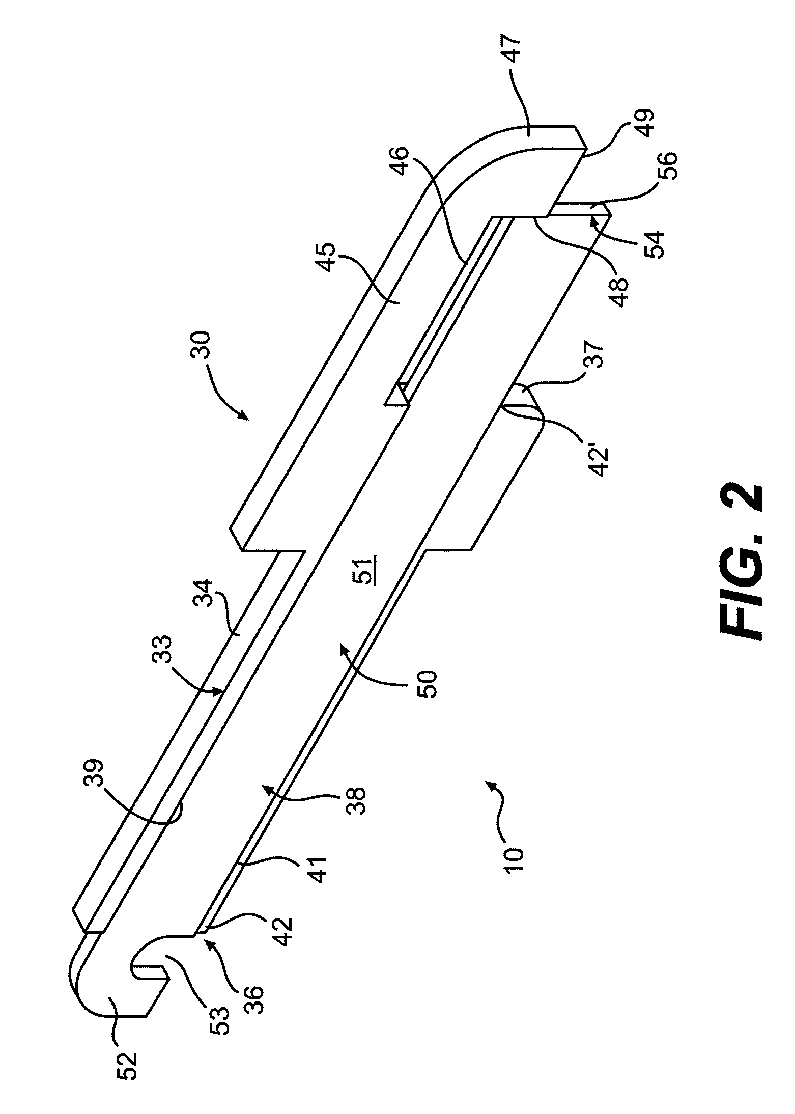
[0009]When the clips are in their extended, engaging positions, the flat front edges of each selected clip is adapted to engage and bear against the rear edge of the hooked front end of its associated level cut loop looper without extending past or beneath the lower edge of the hook front end. As a result, the space behind the hooked front end of the selected level cut loop looper is closed so as to prevent the formation and capture of loops of yarn along the throat portions of the level cut loop loopers. As a further result, the loops of yarn that are formed about th

Problems solved by technology

A problem that exists with many conventional level cut looper / hook assemblies is, however, that the loops of yarn being formed about the clips and hooks when the clips are in their extended position often are not uniformly formed, especially in comparison with the cut pile tufts, which can result in a pile height differential between the cut and loop pile tufts.

Method used


Image

  • Level cut loop looper and clip assembly
  • Level cut loop looper and clip assembly
  • Level cut loop looper and clip assembly

Examples


Embodiment Construction

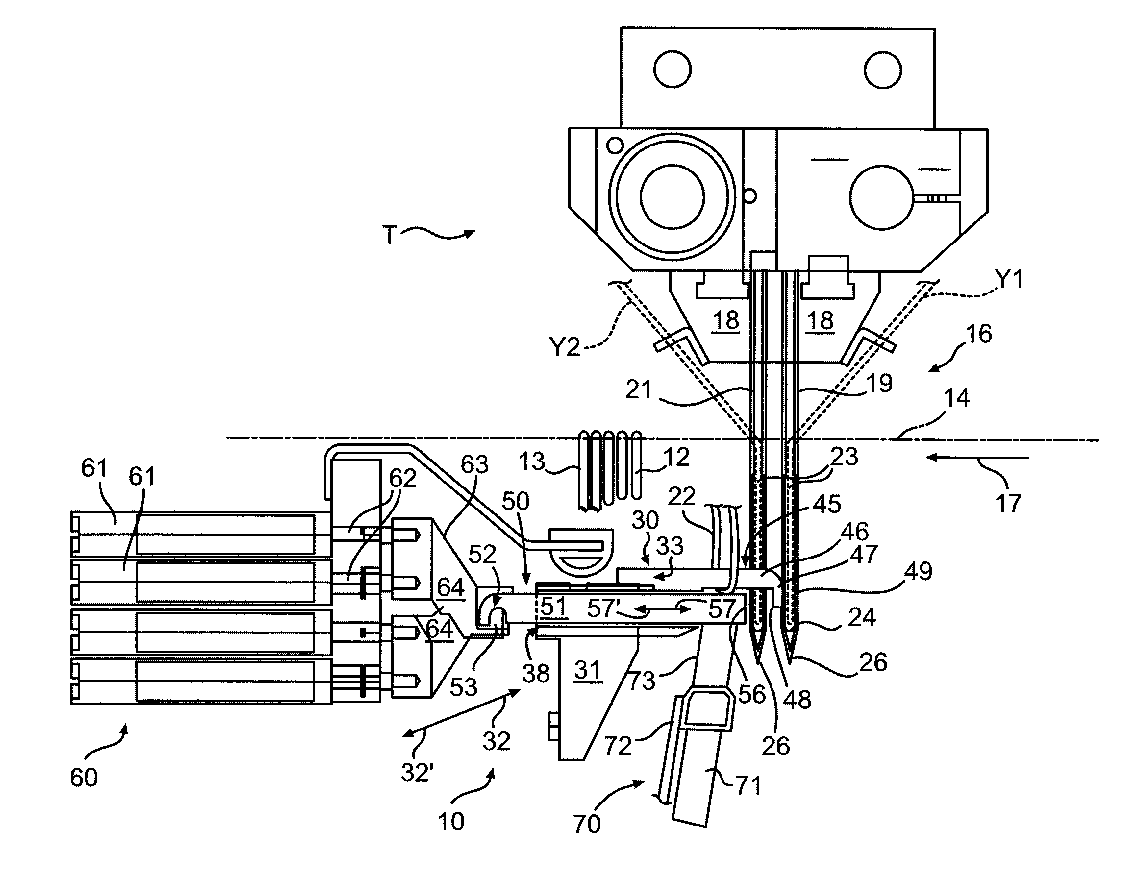
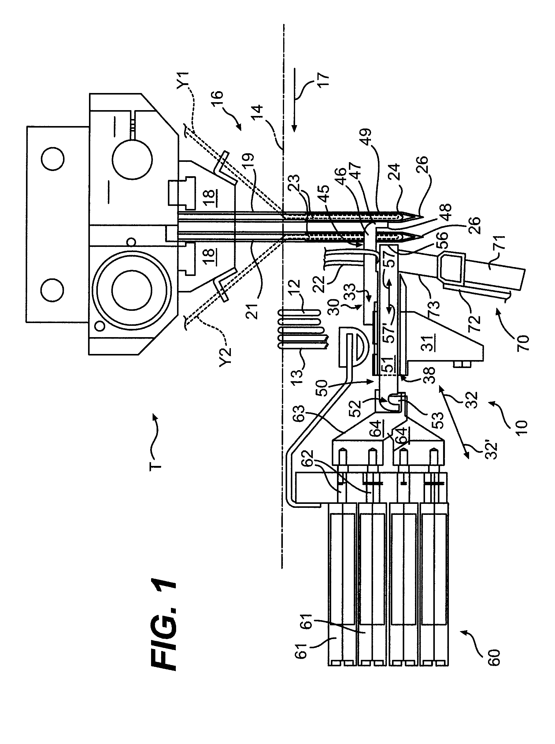
[0016]Referring now in greater detail to the drawings in which like numerals indicate like parts throughout the several views, the present invention generally relates to a level cut loop looper and clip assembly 10 for use in a tufting machine T for forming tufted carpets or similar tufted articles having loop pile and cut pile tufts 12 and 13 (FIG. 1) formed in a backing material 14 as the backing material is fed through a tufting zone 16 of the tufting machine T in the direction of arrow 17. As indicated in FIG. 1, the tufting machine generally will include one or more needle bars 18 that carry a series of spaced needles 19 and 21. The needles 19 and 21 carry a series of yarns Y1 and Y2 as the needles are reciprocated vertically into and out of the backing material so as to form the loop and cut pile tufts 12 and 13, respectively in the backing material.

[0017]Although FIG. 1 illustrates the use of the present invention with a pair of needle bars 18, each including a single row of ...


PUM


Abstract

A level cut loop looper or hook and clip for a tufting machine includes a looper body having a channel in which a clip is received. The clip is moved between extended and retracted positions by an actuator as the level cut loop looper or hook is reciprocated into engagement with a needle of the tufting machine, so as to selectively form cut and loop pile tufts in a backing material.

Description

CROSS REFERENCE TO RELATED APPLICATIONS[0001]The present patent application is a formalization of previously filed, co-pending U.S. provisional patent application Ser. No. 60 / 895,599, filed Mar. 19, 2007, by the inventor named in the present application. This patent application claims the benefit of the filing date of the cited provisional patent application according to the statutes and rules governing provisional patent applications, particularly USC § 119(e)(1) and 37 CFR § 1.78(a)(4) and (a)(5). The specification and drawings of the provisional patent application are specifically incorporated herein by reference.FIELD OF THE INVENTION[0002]The present invention generally relates to tufting carpets and in particular to a new design level cut looper and clip for forming loop and cut pile tufts of yarns in a backing material to form patterned carpets.BACKGROUND OF THE INVENTION[0003]In the field of tufting carpets, it has been known to tuft carpets having spaced rows of loop pile a...

Claims


Application Information

Patent Timeline
IPC IPC(8): D05C15/22D05C15/00
CPCD05C15/22
Inventor HALL, WILTON
Owner CARD MONROE
Learn More